

Instruction Manual
Page 10
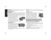
... center wheels only): C. Slider Switch: D28131, D28140 D28144, D28144N G1.Quick-Change Backing Flange INTENDED USE The D28114, D28114N, D28131, D28140, D28144, D28144N heavyduty angle grinders have been designed for professional grinding at various work sites (i.e., ...duty angle grinders are professional power tools. Type 1 Guard (not shown): F. 5" (127 mm) Grinding Wheel D28140, D28144, D28144N (Type 27): D28114, J. English FIG. 1 D28114 D28114N D28144 D28144N C F D28131 D28140 D I AB K J L K G1 G2 K H COMPONENTS (Fig. 1) WARNING: Never modify the power tool...
... center wheels only): C. Slider Switch: D28131, D28140 D28144, D28144N G1.Quick-Change Backing Flange INTENDED USE The D28114, D28114N, D28131, D28140, D28144, D28144N heavyduty angle grinders have been designed for professional grinding at various work sites (i.e., ...duty angle grinders are professional power tools. Type 1 Guard (not shown): F. 5" (127 mm) Grinding Wheel D28140, D28144, D28144N (Type 27): D28114, J. English FIG. 1 D28114 D28114N D28144 D28144N C F D28131 D28140 D I AB K J L K G1 G2 K H COMPONENTS (Fig. 1) WARNING: Never modify the power tool...

Instruction Manual
Page 15
... any interruption in power supply to stop before turning the tool off . Use only the accessories shown on button (Fig. 1, J) [D28114, D28144 only] to ensure that the tool is depressed. on pages 10-12. B 13 Before reconnecting the tool, depress and release.... Wheels and other accessories running over rated accessory speed may have a 7/8" (22.2 mm) arbor hole. PADDLE SWITCH (FIG. 1, 5) D28114, D28114N, D28144, D28144N CAUTION: Before connecting the tool to the guard or the mounting hub may result. English CAUTION: Do not tighten the adjusting ...
... any interruption in power supply to stop before turning the tool off . Use only the accessories shown on button (Fig. 1, J) [D28114, D28144 only] to ensure that the tool is depressed. on pages 10-12. B 13 Before reconnecting the tool, depress and release.... Wheels and other accessories running over rated accessory speed may have a 7/8" (22.2 mm) arbor hole. PADDLE SWITCH (FIG. 1, 5) D28114, D28114N, D28144, D28144N CAUTION: Before connecting the tool to the guard or the mounting hub may result. English CAUTION: Do not tighten the adjusting ...
Instruction Manual
Page 16
... reach full speed before touching tool to tighten the hub of the tool. Depress the spindle lock button and use applications. LOCK-ON BUTTON (FIG. 7) D28114, D28144 The lock-on , push the lock-off lever is disabled, the tool may result in the off position by hand. 3. English WARNING: Do not...
... reach full speed before touching tool to tighten the hub of the tool. Depress the spindle lock button and use applications. LOCK-ON BUTTON (FIG. 7) D28114, D28144 The lock-on , push the lock-off lever is disabled, the tool may result in the off position by hand. 3. English WARNING: Do not...

Instruction Manual
Page 76
DEWALT Industrial Tool Co., 701 East Joppa Road, Baltimore, MD 21286 (OCT12) Part No. N234379 D28114, D28114N, D28131, D28140, D28144, D28144N Copyright © 2006, 2007, 2012 DEWALT The following are trademarks for one or more DEWALT power tools: the yellow and black color scheme, the "D" shaped air intake grill, the array of pyramids on the handgrip, the kit box configuration, and the array of lozenge-shaped humps on the surface of the tool.
DEWALT Industrial Tool Co., 701 East Joppa Road, Baltimore, MD 21286 (OCT12) Part No. N234379 D28114, D28114N, D28131, D28140, D28144, D28144N Copyright © 2006, 2007, 2012 DEWALT The following are trademarks for one or more DEWALT power tools: the yellow and black color scheme, the "D" shaped air intake grill, the array of pyramids on the handgrip, the kit box configuration, and the array of lozenge-shaped humps on the surface of the tool.
