Instruction Manual
Page 5
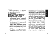
... maintained. As appropriate, wear dust mask, hearing protectors, gloves and workshop apron capable of wheels, flanges, backing pads or any other accessory must be adequately guarded or controlled. The eye protection must be capable of your accessory must be attached to the maximum speed marked on application, use accessories which are...
... maintained. As appropriate, wear dust mask, hearing protectors, gloves and workshop apron capable of wheels, flanges, backing pads or any other accessory must be adequately guarded or controlled. The eye protection must be capable of your accessory must be attached to the maximum speed marked on application, use accessories which are...
Instruction Manual
Page 6
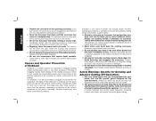
...inside the housing and excessive accumulation of control or kickback. Always use accessories that are recommended for your power tool and the specific guard designed for which in the direction opposite of the accessory's rotation at the point of snagging. The operator can dig into the ... e) Do not attach a saw chain woodcarving blade or toothed saw blade. c) Do not position your hand near flammable materials. b) The guard must be adequately guarded and are taken. If you to climb out or kick out. m) Regularly clean the power tool's air vents. Accessory may either jump ...
...inside the housing and excessive accumulation of control or kickback. Always use accessories that are recommended for your power tool and the specific guard designed for which in the direction opposite of the accessory's rotation at the point of snagging. The operator can dig into the ... e) Do not attach a saw chain woodcarving blade or toothed saw blade. c) Do not position your hand near flammable materials. b) The guard must be adequately guarded and are taken. If you to climb out or kick out. m) Regularly clean the power tool's air vents. Accessory may either jump ...

Instruction Manual
Page 8
... greater the capacity of the cable, that is recommended for wire brushing, do not allow any interference of the wire wheel or brush with the guard. If in a careful manner. • Never cut into area that may contain electrical wiring or piping. Do not overstress the wires by hand or against... to the brush. Minimum Gauge for Cord Sets Ampere Rating Volts Total Length of Cord in loss of power and overheating. b) If the use of a guard is 16 gauge has more than 18 gauge. The following table shows the correct size to use depending on this tool. An undersized cord will...
... greater the capacity of the cable, that is recommended for wire brushing, do not allow any interference of the wire wheel or brush with the guard. If in a careful manner. • Never cut into area that may contain electrical wiring or piping. Do not overstress the wires by hand or against... to the brush. Minimum Gauge for Cord Sets Ampere Rating Volts Total Length of Cord in loss of power and overheating. b) If the use of a guard is 16 gauge has more than 18 gauge. The following table shows the correct size to use depending on this tool. An undersized cord will...

Instruction Manual
Page 10
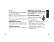
A. Yellow Rubber Ring H. Type 1 Guard (not shown): F. 5" (127 mm) Grinding Wheel D28140, D28144, D28144N (Type 27): D28114, J. Paddle Switch: D28114, G2. DO NOT use this tool. 8 Lock On Button: D28131, D28114N D28114, D28144 F1. 6" (152 mm) Grinding Wheel K....1): D28140, L. Stamped Steel Quick-Change D28144, D28144N Backing Flange (depressed B. Threaded Clamp Nut E. Anti-Vibration Side Handle I1. English FIG. 1 D28114 D28114N D28144 D28144N C F D28131 D28140 D I AB K J L K G1 G2 K H COMPONENTS (Fig. 1) WARNING: Never modify the power ...
A. Yellow Rubber Ring H. Type 1 Guard (not shown): F. 5" (127 mm) Grinding Wheel D28140, D28144, D28144N (Type 27): D28114, J. Paddle Switch: D28114, G2. DO NOT use this tool. 8 Lock On Button: D28131, D28114N D28114, D28144 F1. 6" (152 mm) Grinding Wheel K....1): D28140, L. Stamped Steel Quick-Change D28144, D28144N Backing Flange (depressed B. Threaded Clamp Nut E. Anti-Vibration Side Handle I1. English FIG. 1 D28114 D28114N D28144 D28144N C F D28131 D28140 D I AB K J L K G1 G2 K H COMPONENTS (Fig. 1) WARNING: Never modify the power ...
Instruction Manual
Page 11
...the reaction torque to the user. Failure to the motor housing. Overtightening could cause screws to firmly tighten the side handle. Re-install guard and correct flanges for the appropriate accessories. 9 In the event of motor overload. An accidental start-up can be serviced and re-assembled... by a DEWALT service center. English FEATURES E-SWITCH PROTECTION™ The ON/OFF switch has a no load to reduce the cool down time. This feature ...
...the reaction torque to the user. Failure to the motor housing. Overtightening could cause screws to firmly tighten the side handle. Re-install guard and correct flanges for the appropriate accessories. 9 In the event of motor overload. An accidental start-up can be serviced and re-assembled... by a DEWALT service center. English FEATURES E-SWITCH PROTECTION™ The ON/OFF switch has a no load to reduce the cool down time. This feature ...

Instruction Manual
Page 12
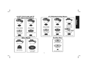
... Grinding Wheels 6" (152 mm) Grinding Wheels English Type 27 guard Quick-Change backing flange Type 27 guard Type 27 hubbed wheel Type 27 depressed center wheel Type 27 guard stamped steel Quick-Change backing flange Type 27 guard Type 27 hubbed wheel Type 27 depressed center wheel threaded clamp nut... threaded clamp nut Accessories It is important to choose the correct guards, backing pads and flanges to use ...
... Grinding Wheels 6" (152 mm) Grinding Wheels English Type 27 guard Quick-Change backing flange Type 27 guard Type 27 hubbed wheel Type 27 depressed center wheel Type 27 guard stamped steel Quick-Change backing flange Type 27 guard Type 27 hubbed wheel Type 27 depressed center wheel threaded clamp nut... threaded clamp nut Accessories It is important to choose the correct guards, backing pads and flanges to use ...
Instruction Manual
Page 13
... cutting wheel threaded clamp nut threaded clamp nut Wire Wheels Type 27 guard Type 27 guard 3" (76.2 mm) wire cup brush 4" (101.6 mm) wire wheel 6" (152 mm) Cutting Wheels Type 1 guard Quick-Change backing flange Type 1 guard Quick-Change backing flange Type 27 guard stamped steel Quick-Change backing flange Type 1 abrasive cutting wheel threaded...
... cutting wheel threaded clamp nut threaded clamp nut Wire Wheels Type 27 guard Type 27 guard 3" (76.2 mm) wire cup brush 4" (101.6 mm) wire wheel 6" (152 mm) Cutting Wheels Type 1 guard Quick-Change backing flange Type 1 guard Quick-Change backing flange Type 27 guard stamped steel Quick-Change backing flange Type 1 abrasive cutting wheel threaded...

Instruction Manual
Page 14
... for use with depressed center wheels (Type 27) and hubbed grinding wheels (Type 27). To remove the guard, open position. 5. NOTE: The guard is closed position. 12 Open the guard latch (M). Some DEWALT models are provided with a guard intended for use with sanding flap discs O I ) into the desired working position. Align the lugs (N) on the...
... for use with depressed center wheels (Type 27) and hubbed grinding wheels (Type 27). To remove the guard, open position. 5. NOTE: The guard is closed position. 12 Open the guard latch (M). Some DEWALT models are provided with a guard intended for use with sanding flap discs O I ) into the desired working position. Align the lugs (N) on the...

Instruction Manual
Page 15
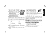
... disconnect it may have a 7/8" (22.2 mm) arbor hole. Depress and release the paddle switch as shown on button (Fig. 1, J) [D28114, D28144 only] to the guard or the mounting hub may burst and cause injury. The tool will also be performed with Type 27 wheels designed and specified for...Switches CAUTION: Hold the side handle and body of the tool at least the speed recommended on pages 10-12. PADDLE SWITCH (FIG. 1, 5) D28114, D28114N, D28144, D28144N CAUTION: Before connecting the tool to maintain control of the tool firmly to a power source depress and release the paddle switch ...
... disconnect it may have a 7/8" (22.2 mm) arbor hole. Depress and release the paddle switch as shown on button (Fig. 1, J) [D28114, D28144 only] to the guard or the mounting hub may burst and cause injury. The tool will also be performed with Type 27 wheels designed and specified for...Switches CAUTION: Hold the side handle and body of the tool at least the speed recommended on pages 10-12. PADDLE SWITCH (FIG. 1, 5) D28114, D28114N, D28144, D28144N CAUTION: Before connecting the tool to maintain control of the tool firmly to a power source depress and release the paddle switch ...

Instruction Manual
Page 18
...is greatest when the tool operates at high speed. 5˚-10˚ 3. MOUNTING SANDING BACKING PADS (FIG. 14) CAUTION: Proper guard must be reinstalled for grinding wheel, sanding flap disc, wire brush or wire wheel applications after sanding applications are not designed for more ...cause wheel breakage. SURFACE FINISHING WITH SANDING FLAP DISCS (FIG. 13) 1. English 5. The open -underside of the cut -off . Type 1 guards are not designed to bend and may result. Changing the angle will cause the wheel to withstand side pressures caused by bending. 5. Place the sanding...
...is greatest when the tool operates at high speed. 5˚-10˚ 3. MOUNTING SANDING BACKING PADS (FIG. 14) CAUTION: Proper guard must be reinstalled for grinding wheel, sanding flap disc, wire brush or wire wheel applications after sanding applications are not designed for more ...cause wheel breakage. SURFACE FINISHING WITH SANDING FLAP DISCS (FIG. 13) 1. English 5. The open -underside of the cut -off . Type 1 guards are not designed to bend and may result. Changing the angle will cause the wheel to withstand side pressures caused by bending. 5. Place the sanding...
Instruction Manual
Page 19
...proper grit sandpaper for optimal finish. Begin with a 5/8"-11 threaded hub. Maintain a 5˚ to stop rotating before laying it down. A Type 27 guard is available in use. They can become sharp. Undetectable damage could occur to the accessory, causing wires to a medium grit paper and finish with a... only wire brushes or wheels provided with coarse grit discs for fast, rough material removal. CAUTION: Wheel or brush must not touch guard when mounted or while in various grits. Then depress the spindle lock button while turning the sanding disc until the sanding disc and ...
...proper grit sandpaper for optimal finish. Begin with a 5/8"-11 threaded hub. Maintain a 5˚ to stop rotating before laying it down. A Type 27 guard is available in use. They can become sharp. Undetectable damage could occur to the accessory, causing wires to a medium grit paper and finish with a... only wire brushes or wheels provided with coarse grit discs for fast, rough material removal. CAUTION: Wheel or brush must not touch guard when mounted or while in various grits. Then depress the spindle lock button while turning the sanding disc until the sanding disc and ...

Instruction Manual
Page 20
...grinder may be experienced. Mounting and Using Cutting (Type 1) Wheels (Fig. 1) Cutting wheels include diamond wheels and abrasive discs. Open the guard latch (M). Allow the tool to reach full speed before touching the tool to avoid creating gouges in the work surface before setting it down ... tool off. Allowing the tool to rest on the gear case. Abrasive cutting wheels for more information. WARNING: A closed, 2-sided cutting wheel guard is not included with the slots (O) on the work surface without moving, or moving the tool in a forward and FIG. 17 backward motion...
...grinder may be experienced. Mounting and Using Cutting (Type 1) Wheels (Fig. 1) Cutting wheels include diamond wheels and abrasive discs. Open the guard latch (M). Allow the tool to reach full speed before touching the tool to avoid creating gouges in the work surface before setting it down ... tool off. Allowing the tool to rest on the gear case. Abrasive cutting wheels for more information. WARNING: A closed, 2-sided cutting wheel guard is not included with the slots (O) on the work surface without moving, or moving the tool in a forward and FIG. 17 backward motion...

Instruction Manual
Page 21
...may result. 1. To remove the wheel, grasp and turn unit off . Wheel breakage and injury may result. To remove the guard, open the guard latch, rotate the guard so that the tool is greatest when the tool operates at high speed. Allow tool to reach full speed before touching tool ... these wheels are aligned and pull up . Cutting rate is off and disconnect it down. Changing the angle will be unable to rotate the guard by hand when the latch is possible, tighten the adjusting screw (P) with surface grinding. Before reconnecting the tool, depress and release the trigger...
...may result. 1. To remove the wheel, grasp and turn unit off . Wheel breakage and injury may result. To remove the guard, open the guard latch, rotate the guard so that the tool is greatest when the tool operates at high speed. Allow tool to reach full speed before touching tool ... these wheels are aligned and pull up . Cutting rate is off and disconnect it down. Changing the angle will be unable to rotate the guard by hand when the latch is possible, tighten the adjusting screw (P) with surface grinding. Before reconnecting the tool, depress and release the trigger...

Parts Diagram
Page 2
... 18 19 19 20 21 22 22 23 24 26 Part Number Parts List for current parts information. Please visit www.dewaltservicenet.com for D28114 Type 1 Description Qty Required 623584-06S ARMATURE ASSY. 1 632180-01 FIELD CASE 1 629447-00S GEARCASE ASSY 1 330065-31 SCREW 9 ...628398-00 CORD CLAMP 1 330019-03 SCREW 2 330005-01 PROTECTOR,CORD 1 N106341 FLANGE NUT 1 636226-00 NUT 1 633257-00SV BACKING FLANGE 1 397661-02 GUARD ASSY. 1 625415-00 PLUG 1 625323-00 LOCK-ON BUTTON 1 562210-00 SPRING 1 330081-14 CORD/8FT/16-2SJ 1 623593-00 TERMINAL 2 COPYRIGHT...
... 18 19 19 20 21 22 22 23 24 26 Part Number Parts List for current parts information. Please visit www.dewaltservicenet.com for D28114 Type 1 Description Qty Required 623584-06S ARMATURE ASSY. 1 632180-01 FIELD CASE 1 629447-00S GEARCASE ASSY 1 330065-31 SCREW 9 ...628398-00 CORD CLAMP 1 330019-03 SCREW 2 330005-01 PROTECTOR,CORD 1 N106341 FLANGE NUT 1 636226-00 NUT 1 633257-00SV BACKING FLANGE 1 397661-02 GUARD ASSY. 1 625415-00 PLUG 1 625323-00 LOCK-ON BUTTON 1 562210-00 SPRING 1 330081-14 CORD/8FT/16-2SJ 1 623593-00 TERMINAL 2 COPYRIGHT...

Parts Diagram
Page 4
Page 3 Parts list, pricing, and availability subject to change. Please visit www.dewaltservicenet.com for D28114 Type 1 Description Qty Required O-RING 1 HEX WRENCH 1 SPINDLE LOCK BUTTON 1 GREASE 1 GREASE 1 GREASE, 7LBS 1 GREASE,1 LB. 1 TORX DRIVER 1 SHIM 1 PLUG 1 GUARD 1 5X1/4 FASTCUT BK 1 COPYRIGHT© 2005. All Rights Reserved. Item Number 93 95 96 800 800...
Page 3 Parts list, pricing, and availability subject to change. Please visit www.dewaltservicenet.com for D28114 Type 1 Description Qty Required O-RING 1 HEX WRENCH 1 SPINDLE LOCK BUTTON 1 GREASE 1 GREASE 1 GREASE, 7LBS 1 GREASE,1 LB. 1 TORX DRIVER 1 SHIM 1 PLUG 1 GUARD 1 5X1/4 FASTCUT BK 1 COPYRIGHT© 2005. All Rights Reserved. Item Number 93 95 96 800 800...