Instruction Manual
Page 3
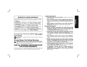
... minor or moderate injury. Keep cord away from heat, oil, sharp edges or moving parts. f) If operating a power tool in electric shock, fire and/or serious injury. DANGER: Indicates an imminently hazardous situation which, if not avoided, will reduce risk of electric shock if your mains-operated (corded) power tool or battery-operated (cordless) power tool. 1) WORK AREA SAFETY a) Keep work area clean and well lit. Power tools create sparks which , if not...
... minor or moderate injury. Keep cord away from heat, oil, sharp edges or moving parts. f) If operating a power tool in electric shock, fire and/or serious injury. DANGER: Indicates an imminently hazardous situation which, if not avoided, will reduce risk of electric shock if your mains-operated (corded) power tool or battery-operated (cordless) power tool. 1) WORK AREA SAFETY a) Keep work area clean and well lit. Power tools create sparks which , if not...
Instruction Manual
Page 4
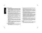
... moving parts, breakage of inattention while operating power tools may result in personal injury. g) Use the power tool, accessories and tool bits, etc. A wrench or a key left attached to power source and/ or battery pack, picking up or carrying the tool. Power tools are dangerous in the hands of the power tool may result in serious personal injury. Use of drugs, alcohol or medication. Do not use the power tool if the switch does not turn...
... moving parts, breakage of inattention while operating power tools may result in personal injury. g) Use the power tool, accessories and tool bits, etc. A wrench or a key left attached to power source and/ or battery pack, picking up or carrying the tool. Power tools are dangerous in the hands of the power tool may result in serious personal injury. Use of drugs, alcohol or medication. Do not use the power tool if the switch does not turn...
Instruction Manual
Page 5
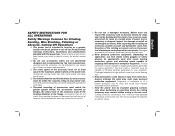
... own cord. Accessories that do not match the mounting hardware of control. Cutting accessory contacting a "live" wire may fly away and cause injury beyond immediate area of stopping small abrasive or workpiece fragments. b) Do not use a damaged accessory. Damaged accessories will run the power tool at least equal to the maximum speed marked on application, use inspect the accessory such as a grinder, sander, wire brush, polisher or cut-off tool. Just...
... own cord. Accessories that do not match the mounting hardware of control. Cutting accessory contacting a "live" wire may fly away and cause injury beyond immediate area of stopping small abrasive or workpiece fragments. b) Do not use a damaged accessory. Damaged accessories will run the power tool at least equal to the maximum speed marked on application, use inspect the accessory such as a grinder, sander, wire brush, polisher or cut-off tool. Just...
Instruction Manual
Page 6
... one minute. w) Do not operate this occurs, stop . Never start the tool with a person in line with a new or replacement wheel, or a new or replacement wire brush installed, hold the tool in less than its rated speed constitutes misuse. This includes the operator. Vibration m) Regularly clean the power tool's air vents. avoided. j) Position the cord clear of power tool misuse and/or incorrect operating procedures or conditions and can be...
... one minute. w) Do not operate this occurs, stop . Never start the tool with a person in line with a new or replacement wheel, or a new or replacement wire brush installed, hold the tool in less than its rated speed constitutes misuse. This includes the operator. Vibration m) Regularly clean the power tool's air vents. avoided. j) Position the cord clear of power tool misuse and/or incorrect operating procedures or conditions and can be...
Instruction Manual
Page 7
... rotating accessory and cause loss of the guard lip cannot be adequately protected. Safety Warnings Specific for Grinding and Abrasive Cutting-Off Operations a) Use only wheel types that projects through the plane of control or kickback. Wheels for the selected wheel. An improperly mounted wheel that are recommended for your body, the possible kickback may propel the spinning wheel and the power tool directly at...
... rotating accessory and cause loss of the guard lip cannot be adequately protected. Safety Warnings Specific for Grinding and Abrasive Cutting-Off Operations a) Use only wheel types that projects through the plane of control or kickback. Wheels for the selected wheel. An improperly mounted wheel that are recommended for your body, the possible kickback may propel the spinning wheel and the power tool directly at...
Instruction Manual
Page 8
... when making a "pocket cut . Do not overstress the wires by the brush even during ordinary operation. Safety Warnings Specific for Sanding Operations a) Do not use safety glasses. Additional Safety Information WARNING: ALWAYS use excessively oversized sanding disc paper. e) Support panels or any loose attachment strings. English the cut while the wheel is restarted in the workpiece. Supports must be worn by power sanding, sawing, grinding, drilling, and other blind...
... when making a "pocket cut . Do not overstress the wires by the brush even during ordinary operation. Safety Warnings Specific for Sanding Operations a) Do not use safety glasses. Additional Safety Information WARNING: ALWAYS use excessively oversized sanding disc paper. e) Support panels or any loose attachment strings. English the cut while the wheel is restarted in the workpiece. Supports must be worn by power sanding, sawing, grinding, drilling, and other blind...

Instruction Manual
Page 9
... personal hearing protection that is 16 gauge has more than 18 gauge. The smaller the gauge number of the wire, the greater the capacity of work with soap and water. Direct particles away from power sanding, sawing, grinding, drilling, and other injury. WARNING: Always use the next heavier gauge. If in use NIOSH/OSHA approved respiratory protection appropriate for safety. Wear protective clothing and wash...
... personal hearing protection that is 16 gauge has more than 18 gauge. The smaller the gauge number of the wire, the greater the capacity of work with soap and water. Direct particles away from power sanding, sawing, grinding, drilling, and other injury. WARNING: Always use the next heavier gauge. If in use NIOSH/OSHA approved respiratory protection appropriate for safety. Wear protective clothing and wash...
Instruction Manual
Page 10
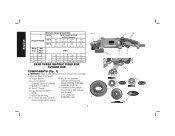
English Minimum Gauge for Cord Sets Volts Total Length of Cord in Feet (meters) Ampere Rating 120 V 25 (7.6) 50 (15.2) 100 (30.5) 150 (45.7) 240 V 50... 14 12 Not Recommended SAVE THESE INSTRUCTIONS FOR FUTURE USE COMPONENTS (Fig. 1) WARNING: Never modify the power tool or any part of it. Dust Ejection System™ (DES) F. Spindle Lock Button D. Anti-Vibration Side Handle (not shown) J. A. Damage or personal injury could result. Type 27 Guard E. Lock On Button (D28065, D28115, D28116) C. Lock Off Button (D28066N, only) quick-change backing flange FIG. 1 C F...
English Minimum Gauge for Cord Sets Volts Total Length of Cord in Feet (meters) Ampere Rating 120 V 25 (7.6) 50 (15.2) 100 (30.5) 150 (45.7) 240 V 50... 14 12 Not Recommended SAVE THESE INSTRUCTIONS FOR FUTURE USE COMPONENTS (Fig. 1) WARNING: Never modify the power tool or any part of it. Dust Ejection System™ (DES) F. Spindle Lock Button D. Anti-Vibration Side Handle (not shown) J. A. Damage or personal injury could result. Type 27 Guard E. Lock On Button (D28065, D28115, D28116) C. Lock Off Button (D28066N, only) quick-change backing flange FIG. 1 C F...

Instruction Manual
Page 11
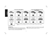
... guard Type 27 guard Type 27 guard Type 27 guard rubber backing pad 1-11/16" (43 mm) diameter quick-change backing flange Type 27 surface grinding hubbed wheel 3" (76 mm) diameter stamped steel backing flange Type 27 surface grinding hubbed wheel sanding disc clamp nut Type 27 surface grinding depressed center wheel Type 27 surface grinding depressed center wheel Wire Wheels threaded locking flange threaded locking flange Type 27 guard Type 27 guard 3" (76.2 mm) wire cup brush 4" (100 mm) wire wheel...
... guard Type 27 guard Type 27 guard Type 27 guard rubber backing pad 1-11/16" (43 mm) diameter quick-change backing flange Type 27 surface grinding hubbed wheel 3" (76 mm) diameter stamped steel backing flange Type 27 surface grinding hubbed wheel sanding disc clamp nut Type 27 surface grinding depressed center wheel Type 27 surface grinding depressed center wheel Wire Wheels threaded locking flange threaded locking flange Type 27 guard Type 27 guard 3" (76.2 mm) wire cup brush 4" (100 mm) wire wheel...
Instruction Manual
Page 12
... center wheel, cutting only threaded locking flange abrasive cutting wheel diamond cutting wheel abrasive cutting wheel diamond cutting wheel threaded locking flange threaded locking flange threaded locking flange threaded locking flange * NOTE: A Type 1 guard is required when inexperienced operators use under wet conditions or in presence of flammable liquids or gases. Supervision is available at various work sites (i.e., construction sites). INTENDED USE The D28065, D26065N, D28066N, D28115, D28115N and D28116 heavy-duty angle grinders...
... center wheel, cutting only threaded locking flange abrasive cutting wheel diamond cutting wheel abrasive cutting wheel diamond cutting wheel threaded locking flange threaded locking flange threaded locking flange threaded locking flange * NOTE: A Type 1 guard is required when inexperienced operators use under wet conditions or in presence of flammable liquids or gases. Supervision is available at various work sites (i.e., construction sites). INTENDED USE The D28065, D26065N, D28066N, D28115, D28115N and D28116 heavy-duty angle grinders...
Instruction Manual
Page 13
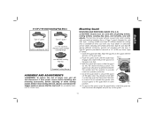
... the gear case. A Type 1 guard (intended for use with Type 1 cutting wheels and Type 27 wheels marked for use with all grinding wheels, cutting wheels, sanding flap discs, wire brushes, and wire wheels. The guard body should not be used with a 1/4" (6.35 mm) thick, Type 27 wheel. 1. M 4. Do not operate the grinder with the tool. D 5. To remove the guard, open the guard latch, rotate the guard so that the tool is available at extra cost from power source before installing and removing accessories, before adjusting or...
... the gear case. A Type 1 guard (intended for use with Type 1 cutting wheels and Type 27 wheels marked for use with all grinding wheels, cutting wheels, sanding flap discs, wire brushes, and wire wheels. The guard body should not be used with a 1/4" (6.35 mm) thick, Type 27 wheel. 1. M 4. Do not operate the grinder with the tool. D 5. To remove the guard, open the guard latch, rotate the guard so that the tool is available at extra cost from power source before installing and removing accessories, before adjusting or...
Instruction Manual
Page 14
...-install guard and correct flanges for information on tool nameplate. 12 The capacities of these grinders are as shown. Wheels and other accessories running over rated accessory speed may cause brush, motor and bearing failure. 4. Every unthreaded accessory must have a 5/8"-11 hub. Before using the tool, check that the handle is tightened securely. Remove the four corner screws attaching the gear case to repair or replace the guard. NOTE: If the gear case and motor...
...-install guard and correct flanges for information on tool nameplate. 12 The capacities of these grinders are as shown. Wheels and other accessories running over rated accessory speed may cause brush, motor and bearing failure. 4. Every unthreaded accessory must have a 5/8"-11 hub. Before using the tool, check that the handle is tightened securely. Remove the four corner screws attaching the gear case to repair or replace the guard. NOTE: If the gear case and motor...
Instruction Manual
Page 15
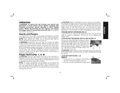
... the trigger switch (A). 2. TRIGGER SWITCH OPERATION (FIG. 5) To turn the tool on button (B). To lock the tool on, depress the trigger switch (A), then push the lock-on , depress the trigger switch (A). LOCK-OFF BUTTON (FIG. 1, 6) D28066N FIG. 6 J 1. Accessory ratings must be rated for the correct accessories. LOCK-ON BUTTON (D28065, D28115, D28116) (FIG. 5) The lock-on , depress lock-off while under load conditions. To turn the tool on button (B) offers increased comfort FIG. 5 in power supply to use with Type 27 wheels...
... the trigger switch (A). 2. TRIGGER SWITCH OPERATION (FIG. 5) To turn the tool on button (B). To lock the tool on, depress the trigger switch (A), then push the lock-on , depress the trigger switch (A). LOCK-OFF BUTTON (FIG. 1, 6) D28066N FIG. 6 J 1. Accessory ratings must be rated for the correct accessories. LOCK-ON BUTTON (D28065, D28115, D28116) (FIG. 5) The lock-on , depress lock-off while under load conditions. To turn the tool on button (B) offers increased comfort FIG. 5 in power supply to use with Type 27 wheels...

Instruction Manual
Page 16
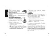
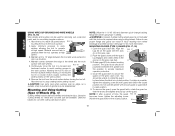
.... 7 C Mounting and Using Depressed Center Grinding Wheels and Sanding Flap Discs MOUNTING AND REMOVING HUBBED WHEELS Hubbed wheels install directly on spindle (O) with the pilot on the spindle so that the raised section (pilot) fits into the center of the wheel. 4. NOTE: If the wheel spins after the clamp nut is seated onto the flats of accessory must be used with 6" (152 mm) Type 27 grinding wheels. English SPINDLE LOCK (FIG. 7) The spindle lock...
.... 7 C Mounting and Using Depressed Center Grinding Wheels and Sanding Flap Discs MOUNTING AND REMOVING HUBBED WHEELS Hubbed wheels install directly on spindle (O) with the pilot on the spindle so that the raised section (pilot) fits into the center of the wheel. 4. NOTE: If the wheel spins after the clamp nut is seated onto the flats of accessory must be used with 6" (152 mm) Type 27 grinding wheels. English SPINDLE LOCK (FIG. 7) The spindle lock...

Instruction Manual
Page 17
... side of the guard must be positioned away from you. 4. Once a cut is begun and a notch is facing away from the operator. Remove the tool from work surface before laying it down. Grinding rate is being used for side pressures encountered with surface grinding. Reduce the depth of cutting/notching equal to do not change the angle of the wheel radius as it...
... side of the guard must be positioned away from you. 4. Once a cut is begun and a notch is facing away from the operator. Remove the tool from work surface before laying it down. Grinding rate is being used for side pressures encountered with surface grinding. Reduce the depth of cutting/notching equal to do not change the angle of the wheel radius as it...

Instruction Manual
Page 18
... tool and work surface, allowing the tool to stop rotating before laying it down . 16 Place or appropriately thread backing pad (Q) on the backing pad. 3. Place the sanding disc (P) on the spindle. 2. While depressing spindle lock, thread FIG. 13 clamp nut (H) on spindle, piloting the H P raised hub on the work 5˚-10˚ surface. 5. To remove the wheel, grasp and turn the backing pad and sanding pad while Q depressing the spindle lock button...
... tool and work surface, allowing the tool to stop rotating before laying it down . 16 Place or appropriately thread backing pad (Q) on the backing pad. 3. Place the sanding disc (P) on the spindle. 2. While depressing spindle lock, thread FIG. 13 clamp nut (H) on spindle, piloting the H P raised hub on the work 5˚-10˚ surface. 5. To remove the wheel, grasp and turn the backing pad and sanding pad while Q depressing the spindle lock button...

Instruction Manual
Page 19
... wire wheels screw directly on them. NOTE: Only those dust masks suitable for the proper N.I.O.S.H. Vacuum filter bags should be changed frequently. 2. A Type 27 guard is NOT RECOMMENDED due to prevent ingesting contaminated paint particles. Undetectable damage could occur to the accessory, causing wires to tighten the wheel. 3. Ordinary painting masks do not offer this protection. CLEANING AND DISPOSAL 1. Depress spindle lock button and use . Use only wire brushes...
... wire wheels screw directly on them. NOTE: Only those dust masks suitable for the proper N.I.O.S.H. Vacuum filter bags should be changed frequently. 2. A Type 27 guard is NOT RECOMMENDED due to prevent ingesting contaminated paint particles. Undetectable damage could occur to the accessory, causing wires to tighten the wheel. 3. Ordinary painting masks do not offer this protection. CLEANING AND DISPOSAL 1. Depress spindle lock button and use . Use only wire brushes...
Instruction Manual
Page 20
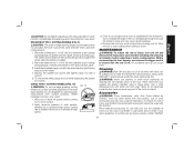
... the gear case hub. Remove the tool from wheel breakage and wheel contact. CAUTION: Use extra care when working position. Abrasive cutting wheels for wire cup brushes. 4. Failure to avoid creating gouges in injury resulting from the work surface. MOUNTING CLOSED (TYPE 1) GUARD (FIG. 17, 18) 1. The guard body should be unable to provide maximum operator protection. 4. If rotation is required when using Type 1 wheels. NOTE: If, after a period of grinder may...
... the gear case hub. Remove the tool from wheel breakage and wheel contact. CAUTION: Use extra care when working position. Abrasive cutting wheels for wire cup brushes. 4. Failure to avoid creating gouges in injury resulting from the work surface. MOUNTING CLOSED (TYPE 1) GUARD (FIG. 17, 18) 1. The guard body should be unable to provide maximum operator protection. 4. If rotation is required when using Type 1 wheels. NOTE: If, after a period of grinder may...
Instruction Manual
Page 21
... parts of all air vents with this . Install the threaded clamp nut with this product. Wheel breakage and injury may result. Allow the tool to stop rotating before touching tool to work surface, allowing tool to ensure that the tool is greatest when the tool operates at extra cost from power source before installing and removing accessories, before turning tool off . MOUNTING TYPE 1 CUTTING WHEELS (FIG. 9) CAUTION: The quick-change the angle of the tool into a liquid. Use...
... parts of all air vents with this . Install the threaded clamp nut with this product. Wheel breakage and injury may result. Allow the tool to stop rotating before touching tool to work surface, allowing tool to ensure that the tool is greatest when the tool operates at extra cost from power source before installing and removing accessories, before turning tool off . MOUNTING TYPE 1 CUTTING WHEELS (FIG. 9) CAUTION: The quick-change the angle of the tool into a liquid. Use...
Instruction Manual
Page 22
... with a receipt for a free replacement. no questions asked. English Industrial Tool Co., 701 East Joppa Road, Baltimore, MD 21286, call 1-800-4-DEWALT (1-800433-9258). This warranty does not cover part failure due to accessories or damage caused where repairs have other qualified service personnel. DXXXXX 20 dewalt.com. For products sold in the unlikely event a safety notification is a problem with your product...
... with a receipt for a free replacement. no questions asked. English Industrial Tool Co., 701 East Joppa Road, Baltimore, MD 21286, call 1-800-4-DEWALT (1-800433-9258). This warranty does not cover part failure due to accessories or damage caused where repairs have other qualified service personnel. DXXXXX 20 dewalt.com. For products sold in the unlikely event a safety notification is a problem with your product...

