Instruction Manual
Page 3
... any adapter plugs with earthed (grounded) power tools. c) Do not expose power tools to follow the warnings and instructions may result in property damage. d) Do not abuse the cord. Never use any way. NOTICE: Indicates a practice not related to your body is an increased risk of electric shock if your mains-operated (corded) power tool or battery-operated (cordless) power tool. 1) WORK AREA SAFETY a) Keep work area clean and well lit. Power tools...
... any adapter plugs with earthed (grounded) power tools. c) Do not expose power tools to follow the warnings and instructions may result in property damage. d) Do not abuse the cord. Never use any way. NOTICE: Indicates a practice not related to your body is an increased risk of electric shock if your mains-operated (corded) power tool or battery-operated (cordless) power tool. 1) WORK AREA SAFETY a) Keep work area clean and well lit. Power tools...
Instruction Manual
Page 4
.... 4) POWER TOOL USE AND CARE a) Do not force the power tool. Use of dust collection can be caught in the off position before turning the power tool on and off. f) Keep cutting tools sharp and clean. Use of a GFCI reduces the risk of electric shock. 3) PERSONAL SAFETY a) Stay alert, watch what you are doing and use common sense when operating a power tool. d) Remove any adjusting key or wrench before connecting to a rotating part of...
.... 4) POWER TOOL USE AND CARE a) Do not force the power tool. Use of dust collection can be caught in the off position before turning the power tool on and off. f) Keep cutting tools sharp and clean. Use of a GFCI reduces the risk of electric shock. 3) PERSONAL SAFETY a) Stay alert, watch what you are doing and use common sense when operating a power tool. d) Remove any adjusting key or wrench before connecting to a rotating part of...
Instruction Manual
Page 5
...; An extension cord must have adequate wire size (AWG or American Wire Gauge) for safety. Wear a dust mask or respirator for Heavy Duty Rotary Hammers • Wear ear protectors. Badly worn chisels require reforging. The smaller the gauge number of the wire, the greater the capacity of power and overheating. When using only identical replacement parts. Moving bits could give the opeartor an electric shock. • Use clamps or other...
...; An extension cord must have adequate wire size (AWG or American Wire Gauge) for safety. Wear a dust mask or respirator for Heavy Duty Rotary Hammers • Wear ear protectors. Badly worn chisels require reforging. The smaller the gauge number of the wire, the greater the capacity of power and overheating. When using only identical replacement parts. Moving bits could give the opeartor an electric shock. • Use clamps or other...
Instruction Manual
Page 6
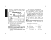
... • arsenic and chromium from power sanding, sawing, grinding, drilling, and other injury. direct current ........alternating or Class I Construction grounded) direct current no .........no load speed Class II Construction n ...........rated speed double insulated) ..........earthing terminal 4 Minimum Gauge for the dust exposure. To reduce your mouth, eyes, or lay on cord length and nameplate ampere rating. Always use safety glasses. The symbols and their definitions...
... • arsenic and chromium from power sanding, sawing, grinding, drilling, and other injury. direct current ........alternating or Class I Construction grounded) direct current no .........no load speed Class II Construction n ...........rated speed double insulated) ..........earthing terminal 4 Minimum Gauge for the dust exposure. To reduce your mouth, eyes, or lay on cord length and nameplate ampere rating. Always use safety glasses. The symbols and their definitions...
Instruction Manual
Page 7
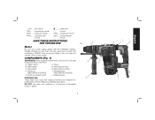
... minute RPM ........ if this tool does not operate, check power supply. Trigger switch F. Mode selection dial C. Depth rod release button J. Damage or personal injury could result. Side handle H. Depth rod (only D25413 & D25415) I English DO NOT use under wet conditions or in presence of it. .../min ..... Chuck B. beats per minute SAVE THESE INSTRUCTIONS FOR FUTURE USE F FIG. 1 G Motor Be sure your power supply agrees with the...
... minute RPM ........ if this tool does not operate, check power supply. Trigger switch F. Mode selection dial C. Depth rod release button J. Damage or personal injury could result. Side handle H. Depth rod (only D25413 & D25415) I English DO NOT use under wet conditions or in presence of it. .../min ..... Chuck B. beats per minute SAVE THESE INSTRUCTIONS FOR FUTURE USE F FIG. 1 G Motor Be sure your power supply agrees with the...
Instruction Manual
Page 8
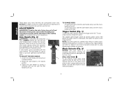
... -hand users: slide the side handle clamp over the chuck, handle at the right. To stop before adjusting or when making repairs. Mode Selector (Fig. 3) NOTICE: Tool must come into contact with this tool. Rotate the side handle to the corresponding symbol as shown. The farther the trigger switch is required when inexperienced operators use drill-only mode, press mode selector button (H) and turn unit off and disconnect it from power...
... -hand users: slide the side handle clamp over the chuck, handle at the right. To stop before adjusting or when making repairs. Mode Selector (Fig. 3) NOTICE: Tool must come into contact with this tool. Rotate the side handle to the corresponding symbol as shown. The farther the trigger switch is required when inexperienced operators use drill-only mode, press mode selector button (H) and turn unit off and disconnect it from power...
Instruction Manual
Page 9
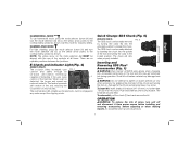
... by inserting the chuck into the spindle of the tool and turning the collar to tighten or loosen drill bits (or any mode except the chipping mode. ALWAYS wear gloves when changing bits. Accessible metal parts on the mode selection dial MUST be securely held. Small bits of the hammer. Use this mode for masonry drilling. The red indicator LED (J) lights up can be easily removed by...
... by inserting the chuck into the spindle of the tool and turning the collar to tighten or loosen drill bits (or any mode except the chipping mode. ALWAYS wear gloves when changing bits. Accessible metal parts on the mode selection dial MUST be securely held. Small bits of the hammer. Use this mode for masonry drilling. The red indicator LED (J) lights up can be easily removed by...

Instruction Manual
Page 10
... injury, ALWAYS use proper hand position as shown in and hold securely in drill-only mode. Proper hand position requires one hand on the side handle (C), with the depth rod, stop when end of rod reaches surface of the bit equals the desired drilling depth. 3. To reverse the rotary hammer, turn the rotary hammer off and position the reversing lever (H) to reverse the rotary hammer for forward operation, turn it off...
... injury, ALWAYS use proper hand position as shown in and hold securely in drill-only mode. Proper hand position requires one hand on the side handle (C), with the depth rod, stop when end of rod reaches surface of the bit equals the desired drilling depth. 3. To reverse the rotary hammer, turn the rotary hammer off and position the reversing lever (H) to reverse the rotary hammer for forward operation, turn it off...
Instruction Manual
Page 11
... WOOD, use spade bits, power auger bits, or hole saws. For METAL, use sharp drill bits. For MASONRY, such as brick, cement, cinder block, etc., use a wood "back-up with the same twist drills used . Hold tool firmly to full power while applying firm pressure on the tool. DO NOT CLICK TRIGGER ON AND OFF IN AN ATTEMPT TO START A STALLED DRILL - With variable speed drills there is no need to...
... WOOD, use spade bits, power auger bits, or hole saws. For METAL, use sharp drill bits. For MASONRY, such as brick, cement, cinder block, etc., use a wood "back-up with the same twist drills used . Hold tool firmly to full power while applying firm pressure on the tool. DO NOT CLICK TRIGGER ON AND OFF IN AN ATTEMPT TO START A STALLED DRILL - With variable speed drills there is no need to...

Instruction Manual
Page 12
... the bit at least once a week. Adjust the side handle (C) as this tool could be used in locating any liquid get inside the tool; English 2. never immerse any part of the hole with clean, dry air at a right angle to help clear debris from power source before installing and removing accessories, before adjusting or when making repairs. Set the mode selector switch (G) to 25 mm) Concrete No-load...
... the bit at least once a week. Adjust the side handle (C) as this tool could be used in locating any liquid get inside the tool; English 2. never immerse any part of the hole with clean, dry air at a right angle to help clear debris from power source before installing and removing accessories, before adjusting or when making repairs. Set the mode selector switch (G) to 25 mm) Concrete No-load...
Instruction Manual
Page 13
... online at www.dewalt.com/register. This warranty does not cover part failure due to products sold in Latin America, see country specific warranty information contained in the unlikely event a safety notification is a problem with a receipt for a free replacement. 11 This warranty does not apply to the warranty, DEWALT tools are covered by our: 1 YEAR FREE SERVICE DEWALT will maintain the tool and replace worn parts caused by normal use identical replacement parts...
... online at www.dewalt.com/register. This warranty does not cover part failure due to products sold in Latin America, see country specific warranty information contained in the unlikely event a safety notification is a problem with a receipt for a free replacement. 11 This warranty does not apply to the warranty, DEWALT tools are covered by our: 1 YEAR FREE SERVICE DEWALT will maintain the tool and replace worn parts caused by normal use identical replacement parts...

Instruction Manual
Page 44
the array of pyramids on the surface of lozenge-shaped humps on the handgrip; and the array of the tool. the kit box configuration; N362625 D25413, D25415, D25430 Copyright © 2013 DEWALT The following are trademarks for one or more DEWALT power tools: the yellow and black color scheme; DEWALT Industrial Tool Co., 701 East Joppa Road, Baltimore, MD 21286 (NOV13) Part No. the "D" shaped air intake grill;
the array of pyramids on the surface of lozenge-shaped humps on the handgrip; and the array of the tool. the kit box configuration; N362625 D25413, D25415, D25430 Copyright © 2013 DEWALT The following are trademarks for one or more DEWALT power tools: the yellow and black color scheme; DEWALT Industrial Tool Co., 701 East Joppa Road, Baltimore, MD 21286 (NOV13) Part No. the "D" shaped air intake grill;


