
Service Manual
Page 1
...PARTS LIST PRINTED WIRING BOARD PARTS LIST PARTS LIST OF EXPLODED VIEW EXPLODED VIEW OF CHASSIS AND CABINET EXPLODED VIEW OF CD MECHANISM PARTS LIST OF CD MECHANISM BLOCK DIAGRAM WIRING DIAGRAM PARTS LIST OF ACCESSORIES AND PACKING VIEW SCHEMATIC DIAGRAM 2-8 8 9-11 12,13 14,15... illustration using in this service manual is slightly different from the actual set. NIPPON COLUMBIA CO.. LTD. CONTENTS - " a 0000 - V22910 DENON Hi-Fi Component SERVICE MANUAL MODEL DCD-425 MODEL DCD-335 STEREO CD PLAYER DENON J 0 DCD-425 onI -„ ) Ei aaaa 21.660O 6a 96 a 1:2g OO000 O0 DEN0N _d...
...PARTS LIST PRINTED WIRING BOARD PARTS LIST PARTS LIST OF EXPLODED VIEW EXPLODED VIEW OF CHASSIS AND CABINET EXPLODED VIEW OF CD MECHANISM PARTS LIST OF CD MECHANISM BLOCK DIAGRAM WIRING DIAGRAM PARTS LIST OF ACCESSORIES AND PACKING VIEW SCHEMATIC DIAGRAM 2-8 8 9-11 12,13 14,15... illustration using in this service manual is slightly different from the actual set. NIPPON COLUMBIA CO.. LTD. CONTENTS - " a 0000 - V22910 DENON Hi-Fi Component SERVICE MANUAL MODEL DCD-425 MODEL DCD-335 STEREO CD PLAYER DENON J 0 DCD-425 onI -„ ) Ei aaaa 21.660O 6a 96 a 1:2g OO000 O0 DEN0N _d...
Service Manual
Page 2
... or polarization means of the type described in the operating instructions should be retained for U.S.A. DCD-425 Serial No. it by pulling the cord. 2. LABELS (for future reference. routed so ... Inside Do not place metal olhects or spill liquid inside the CO player. NOTE: This CD player uses the semiconductor laser. Power-supply cords should be • ca tions should be...and the point where they are not spilled into the appliance; Nonuse Periods -The power cord of your DENON DEALER. 3. or E. IMPORTANT TO SAFETY WARNING: TO PREVENT FIRE OR SHOCK HAZARD, DO NOT EXPOSE...
... or polarization means of the type described in the operating instructions should be retained for U.S.A. DCD-425 Serial No. it by pulling the cord. 2. LABELS (for future reference. routed so ... Inside Do not place metal olhects or spill liquid inside the CO player. NOTE: This CD player uses the semiconductor laser. Power-supply cords should be • ca tions should be...and the point where they are not spilled into the appliance; Nonuse Periods -The power cord of your DENON DEALER. 3. or E. IMPORTANT TO SAFETY WARNING: TO PREVENT FIRE OR SHOCK HAZARD, DO NOT EXPOSE...
Service Manual
Page 3
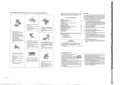
sole. ter, and dust. • Proteger l'appareil contre l'humidite, ('eau et la poussiere. • Mantenga et equipo libre de hume- l.i ... , 4 • Unplug the power cord when not using the set . • No pas mettre en contact des insecticides, du benzene et un diluent avec l'appareil. • No permita el contacto de insecticides, gasoline y diluyenles con el equipo. • Handle the power cord carefully. Hold the plug when unplugging the cord. • Marapuler le cordon d'alimentation avec preprecaution. g .. ..-._ • 1)•ti--,44.... • Keep the set . &#...
sole. ter, and dust. • Proteger l'appareil contre l'humidite, ('eau et la poussiere. • Mantenga et equipo libre de hume- l.i ... , 4 • Unplug the power cord when not using the set . • No pas mettre en contact des insecticides, du benzene et un diluent avec l'appareil. • No permita el contacto de insecticides, gasoline y diluyenles con el equipo. • Handle the power cord carefully. Hold the plug when unplugging the cord. • Marapuler le cordon d'alimentation avec preprecaution. g .. ..-._ • 1)•ti--,44.... • Keep the set . &#...
Service Manual
Page 4
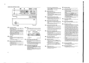
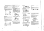
.... Also, when this button for prograrnmed playback (Refer to the number of tracks on the disc is auto- Disc Holder • Place the disc on a CD are automatically split into sections, such as displays for the second half, after which was previously displayed. liPause indicator Ray indicator A-B repeat indicator Open/Close...
.... Also, when this button for prograrnmed playback (Refer to the number of tracks on the disc is auto- Disc Holder • Place the disc on a CD are automatically split into sections, such as displays for the second half, after which was previously displayed. liPause indicator Ray indicator A-B repeat indicator Open/Close...
Service Manual
Page 5
...connect the left IL) and right IRI output terminal CLINE OUT) of the DCD-425 to dust or dirt on the disc, the indicators will read as this may cause malfunction and damage the CD player. 8 rs NORMAL CD PLAYBACK 111 Starting Playback ; Press the OPEN/CLOSE button I during playback ...the calendar. 0 Programming with the inner tray guide circumference. (Fig. 21 • Press the OPEN/CLOSE button 1:I is equipped with a DENON cassette deck which is pressed, playback will start immediately upon the disc contents having been read and the number of tracks and total playing time...
...connect the left IL) and right IRI output terminal CLINE OUT) of the DCD-425 to dust or dirt on the disc, the indicators will read as this may cause malfunction and damage the CD player. 8 rs NORMAL CD PLAYBACK 111 Starting Playback ; Press the OPEN/CLOSE button I during playback ...the calendar. 0 Programming with the inner tray guide circumference. (Fig. 21 • Press the OPEN/CLOSE button 1:I is equipped with a DENON cassette deck which is pressed, playback will start immediately upon the disc contents having been read and the number of tracks and total playing time...
Service Manual
Page 6
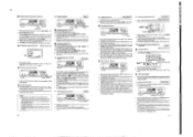
DENON nc) EL • ( REPEAT ) I le/II PLAY/ PAUSEI O Repeating playback of the track is displayed. • Steps 0 and 121 above may be repeated until the ... random order. kt O ; the I ) Playing in a different order. The corresponding track number lights on the calendar, the track number is displayed. • Steps 0.19 and CD above may be displayed for the desired track 2. Press the automatic search buttons 11•14 041 again. The operations in random order. • If...
DENON nc) EL • ( REPEAT ) I le/II PLAY/ PAUSEI O Repeating playback of the track is displayed. • Steps 0 and 121 above may be repeated until the ... random order. kt O ; the I ) Playing in a different order. The corresponding track number lights on the calendar, the track number is displayed. • Steps 0.19 and CD above may be displayed for the desired track 2. Press the automatic search buttons 11•14 041 again. The operations in random order. • If...
Service Manual
Page 7
...10 seconds from the current track or the next track. 113) Synchronized Recording Function Synchronized Recording Function Connecting the SYNCHRO jack with a DENON cassette deck which is equipped with numbers from 11 and on, first press the +10 button and then a single-digit button. ...deck and the cassette deck becomes synchronized pause condition. Replacement may be difficult to operate it towards the remotesontrol sensor on the CD player and remote control unit simultaneously as direct sunlight or light frdm fluorescent lamps. Track Selection Use the nano,c track buttons II...
...10 seconds from the current track or the next track. 113) Synchronized Recording Function Synchronized Recording Function Connecting the SYNCHRO jack with a DENON cassette deck which is equipped with numbers from 11 and on, first press the +10 button and then a single-digit button. ...deck and the cassette deck becomes synchronized pause condition. Replacement may be difficult to operate it towards the remotesontrol sensor on the CD player and remote control unit simultaneously as direct sunlight or light frdm fluorescent lamps. Track Selection Use the nano,c track buttons II...
Service Manual
Page 8
...feeder cable is turned off with hair dryers. See page 8 • Have programming been properly done? co TIMER-CONTROLLED PLAYBACK II Connection O DCD-425 00 0 I is loaded, Woo ooeo Is displayed. Make sure a disc has been loaded in the center of all components connected to be...space. interference could occur either in the cases when they are subject to change without notice in particular when removing a disc from the CD player? in the course of Channels: Frequency Response: Dynamic Rang*: Signal-to strong light? • Are the batteries exhausted? or ...
...feeder cable is turned off with hair dryers. See page 8 • Have programming been properly done? co TIMER-CONTROLLED PLAYBACK II Connection O DCD-425 00 0 I is loaded, Woo ooeo Is displayed. Make sure a disc has been loaded in the center of all components connected to be...space. interference could occur either in the cases when they are subject to change without notice in particular when removing a disc from the CD player? in the course of Channels: Frequency Response: Dynamic Rang*: Signal-to strong light? • Are the batteries exhausted? or ...

Service Manual
Page 9
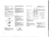
... numerals may be expressed as 565, but Oct. Note: The numbers of the Components +Z-axis direction Ob'ect lens Actuator cover Slide base CICO425/335 CD Slide rack Soldered short circuit portion(Rear side) Label 1. Serial number O O O O O 2. O O but Name • late the head of X, Y and...
... numerals may be expressed as 565, but Oct. Note: The numbers of the Components +Z-axis direction Ob'ect lens Actuator cover Slide base CICO425/335 CD Slide rack Soldered short circuit portion(Rear side) Label 1. Serial number O O O O O 2. O O but Name • late the head of X, Y and...
Service Manual
Page 10
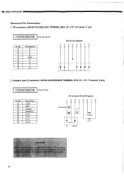
...; 0 © © CD 0 Description Laser GND monitor reference Fo (-) Tr (+) Tr (-) Fo (+) LD Actuator Circuit Diagram 12 3 4 567 8 Short-round r LD Monitor Tracking Focus CAUTION ck-up section, ... LD connector (JAPAN SOLDERLESS TERMINAL MFG CO. PD connector (JAPAN SOLDERLESS TERMINAL MFG CO. LTD "PH series" 8 pin) 00400000 COLOR: WHITE Pin No. 0 © © CD © © CD CD PD element F E K GND A B C D PD Circuit Diagram 123456 7 8 2. LTD "PH series" 8 pin) 00000000 COLOR: RED Pin No. DCD-425/335 Electrical Pin Connection 1.
...; 0 © © CD 0 Description Laser GND monitor reference Fo (-) Tr (+) Tr (-) Fo (+) LD Actuator Circuit Diagram 12 3 4 567 8 Short-round r LD Monitor Tracking Focus CAUTION ck-up section, ... LD connector (JAPAN SOLDERLESS TERMINAL MFG CO. PD connector (JAPAN SOLDERLESS TERMINAL MFG CO. LTD "PH series" 8 pin) 00400000 COLOR: WHITE Pin No. 0 © © CD © © CD CD PD element F E K GND A B C D PD Circuit Diagram 123456 7 8 2. LTD "PH series" 8 pin) 00000000 COLOR: RED Pin No. DCD-425/335 Electrical Pin Connection 1.

Service Manual
Page 13
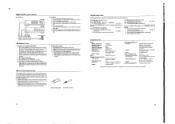
DC0425/335 - 3. o o CD Mechanism © 0 0 O 4. Rear Panel © 1) Remove 2 screws and 5 screws Q. 2) Remove the Cord Bush. 3) Unfasten 3 hooks and detach the Rear Panel in the arrow direction. CD Mechanism Remove 4 screws © and detach the CD mecanism in the arrow direction. 0 Hook Cord Bush Rear Panel Hook 0 Hook 13
DC0425/335 - 3. o o CD Mechanism © 0 0 O 4. Rear Panel © 1) Remove 2 screws and 5 screws Q. 2) Remove the Cord Bush. 3) Unfasten 3 hooks and detach the Rear Panel in the arrow direction. CD Mechanism Remove 4 screws © and detach the CD mecanism in the arrow direction. 0 Hook Cord Bush Rear Panel Hook 0 Hook 13
Service Manual
Page 16
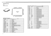
...CDP S2 P CDP S1 P SCOR OP/SW CUSW I/O Ini Function I - O - O - O - O - O - O - O - O - Segment signal output terminal for CD mechanism drive. O - O - Not used (Open). O - O - I L Input signal for FDP. I - I L Not used (Connect to Voo. - i..5O O i-7--I ... /O kg Function - Not used (Open). Serial clock(CH1) input/output signal. - Ground. Segment signal output terminal for FOP. I CICCI-425/335 SEMICONDUCTORS • IC's CXP82316-372O (IC801) 41 O 80 m,FJK]gMEln, Moar. I L Not used (Open). Output signal. - ...
...CDP S2 P CDP S1 P SCOR OP/SW CUSW I/O Ini Function I - O - O - O - O - O - O - O - O - Segment signal output terminal for CD mechanism drive. O - O - Not used (Open). O - O - I L Input signal for FDP. I - I L Not used (Connect to Voo. - i..5O O i-7--I ... /O kg Function - Not used (Open). Serial clock(CH1) input/output signal. - Ground. Segment signal output terminal for FOP. I CICCI-425/335 SEMICONDUCTORS • IC's CXP82316-372O (IC801) 41 O 80 m,FJK]gMEln, Moar. I L Not used (Open). Output signal. - ...
Service Manual
Page 26
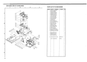
... 319 3x10 screw 2 B 960 9002 332 2.6x5 screw 2 C DCD 2150 321 3x8 screw 1 D 960 9002 329 Mecha screw 4 W1 960 0038 703 Feed mecha Assy KSM2101ADM 1 499 0171 003 Optical pickup KSS210A 1 Part No. I 000425/335 EXPLODED VIEW OF CD MECANISM 1 i 2 3 4 A A 1 2 3 4 B 5 22 6 7 8 9 10 11 c=) C gob D MOM 19 ...• • 13 14 15 16 17 18 GO • 20 23 24 D 21 E 26 PARTS LIST OF CD MECHANISM Ref. Part Name 1 DCD 2150 311 Clamper plate 2 DCD 2150 315 Flapper 3 960 0059 708 Magnet core 4 960 0059 601 Disc damper 5 960 0059 504 Guide frame 6 960 0059...
... 319 3x10 screw 2 B 960 9002 332 2.6x5 screw 2 C DCD 2150 321 3x8 screw 1 D 960 9002 329 Mecha screw 4 W1 960 0038 703 Feed mecha Assy KSM2101ADM 1 499 0171 003 Optical pickup KSS210A 1 Part No. I 000425/335 EXPLODED VIEW OF CD MECANISM 1 i 2 3 4 A A 1 2 3 4 B 5 22 6 7 8 9 10 11 c=) C gob D MOM 19 ...• • 13 14 15 16 17 18 GO • 20 23 24 D 21 E 26 PARTS LIST OF CD MECHANISM Ref. Part Name 1 DCD 2150 311 Clamper plate 2 DCD 2150 315 Flapper 3 960 0059 708 Magnet core 4 960 0059 601 Disc damper 5 960 0059 504 Guide frame 6 960 0059...
Service Manual
Page 31
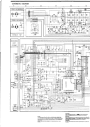
... Co 11101800 Ass CFCT WOW 000 506 COUT AST :4;;IiRgWfiga;g • • • A A 0124 0.033 A 5119 C125 0.047 0202 0.22/30 • R201 100K Fa 1 CD 0.0 WM= a AVDO CLTV AVSS F3LI FILO VOCE VP03 ?C a10 IC V53 P00 TEST • 5001 VCCO • IC • L03( • YDS IMP • 104...
... Co 11101800 Ass CFCT WOW 000 506 COUT AST :4;;IiRgWfiga;g • • • A A 0124 0.033 A 5119 C125 0.047 0202 0.22/30 • R201 100K Fa 1 CD 0.0 WM= a AVDO CLTV AVSS F3LI FILO VOCE VP03 ?C a10 IC V53 P00 TEST • 5001 VCCO • IC • L03( • YDS IMP • 104...


