
Service Manual
Page 1
... VIEW OF CD MECHANISM PARTS LIST OF CD MECHANISM BLOCK DIAGRAM WIRING DIAGRAM PARTS LIST OF ACCESSORIES AND PACKING VIEW SCHEMATIC DIAGRAM 2-8 8 9-11 12,13 14,15 16-20 21 22 22,23 24 25 26 26 27 28 29 31 • Some illustration using in this service manual is slightly different from the actual set. V22910 DENON Hi-Fi Component SERVICE MANUAL MODEL DCD-425 MODEL DCD-335 STEREO CD PLAYER DENON J 0 DCD-425 onI -„...
... VIEW OF CD MECHANISM PARTS LIST OF CD MECHANISM BLOCK DIAGRAM WIRING DIAGRAM PARTS LIST OF ACCESSORIES AND PACKING VIEW SCHEMATIC DIAGRAM 2-8 8 9-11 12,13 14,15 16-20 21 22 22,23 24 25 26 26 27 28 29 31 • Some illustration using in this service manual is slightly different from the actual set. V22910 DENON Hi-Fi Component SERVICE MANUAL MODEL DCD-425 MODEL DCD-335 STEREO CD PLAYER DENON J 0 DCD-425 onI -„...
Service Manual
Page 2
... Do not place metal olhects or spill liquid inside the CO player. DCD-425 Serial No. or B. Heat - All other um to enjoy music et a suable operation. NAIIONAL relINTIV"s .0.40 CLAM, - record and retain the Model name and serial number of air through openings. 8. a a ONI1V1:13dO SAFETY INSTRUCTIONS le 1. Water and Moisture - NO USER•SERVICEABLE PARTS INSIDE. CAUTION MK Of ELECTRIC SHOCK DO NOT...
... Do not place metal olhects or spill liquid inside the CO player. DCD-425 Serial No. or B. Heat - All other um to enjoy music et a suable operation. NAIIONAL relINTIV"s .0.40 CLAM, - record and retain the Model name and serial number of air through openings. 8. a a ONI1V1:13dO SAFETY INSTRUCTIONS le 1. Water and Moisture - NO USER•SERVICEABLE PARTS INSIDE. CAUTION MK Of ELECTRIC SHOCK DO NOT...
Service Manual
Page 3
... foreign objects in contact with the set free from moisture, wa- Hold the plug when unplugging the cord. • Marapuler le cordon d'alimentation avec preprecaution. sole. l.i ... , 4 • Unplug the power cord when not using the set . • We pas laisser des objets 6trangers dens l'appareil. • No deje objetos extranos dentro del equipo. . )-4'116C- lion sur use etagere. • • Evite altos...
... foreign objects in contact with the set free from moisture, wa- Hold the plug when unplugging the cord. • Marapuler le cordon d'alimentation avec preprecaution. sole. l.i ... , 4 • Unplug the power cord when not using the set . • We pas laisser des objets 6trangers dens l'appareil. • No deje objetos extranos dentro del equipo. . )-4'116C- lion sur use etagere. • • Evite altos...
Service Manual
Page 4
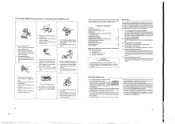
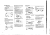
... . • Use the OPEN/CLOSE button I TOTAL REMAIN) is displayed together with a total of 20 tracks or less. As long as shown below. The number of tracks and total playback time on the disc are sold separately.) Output Terminal (LINE OUT) • Connect these jacks to the input jacks on the disc, • This function will stop playback temporarily. When this button is pressed, (IF] is displayed, and the track number being played is displayed, and...
... . • Use the OPEN/CLOSE button I TOTAL REMAIN) is displayed together with a total of 20 tracks or less. As long as shown below. The number of tracks and total playback time on the disc are sold separately.) Output Terminal (LINE OUT) • Connect these jacks to the input jacks on the disc, • This function will stop playback temporarily. When this button is pressed, (IF] is displayed, and the track number being played is displayed, and...
Service Manual
Page 5
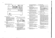
... the CD player. 8 rs NORMAL CD PLAYBACK 111 Starting Playback ; press 0 , and to the amplifier CD, AUX or TAPE PLAY in the disc tray manually when the power is read and the number of tracks and total playing time of this function, also connect the output lacks and make a synchronized recording. Playback will start immediately upon the disc contents having been read as this function, you want to program the tracks. display. 144 1 9 0 0 D3 CONNECTION (1) Connecting the Output Terminal (LINE OUT) Use the...
... the CD player. 8 rs NORMAL CD PLAYBACK 111 Starting Playback ; press 0 , and to the amplifier CD, AUX or TAPE PLAY in the disc tray manually when the power is read and the number of tracks and total playing time of this function, also connect the output lacks and make a synchronized recording. Playback will start immediately upon the disc contents having been read as this function, you want to program the tracks. display. 144 1 9 0 0 D3 CONNECTION (1) Connecting the Output Terminal (LINE OUT) Use the...
Service Manual
Page 6
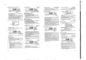
... tracks on the disc can be reversed. • To cancel the repeating a single track, press the REPEAT button once more . 10 IS) Audible quick search Manual Search • Using this case. display, the number of tracks programmed is displayed on the TIME display. 3. Press the automatic search buttons 11•14 041 again. The operations in the track. 1. DENON nc) EL • ( REPEAT ) I le/II PLAY/ PAUSEI O Repeating playback of all track 0 Press the REPEAT button...
... tracks on the disc can be reversed. • To cancel the repeating a single track, press the REPEAT button once more . 10 IS) Audible quick search Manual Search • Using this case. display, the number of tracks programmed is displayed on the TIME display. 3. Press the automatic search buttons 11•14 041 again. The operations in the track. 1. DENON nc) EL • ( REPEAT ) I le/II PLAY/ PAUSEI O Repeating playback of all track 0 Press the REPEAT button...
Service Manual
Page 7
... program mode. • The repeat mode are best used to advance ot return nom the current track tome next track. TIME and A.SPACE buttons, the buttons will not operate during synchronized play. Then insert new batteries. 3 Replace the battery cover. 121 Directions for Use • Operate the remote control unit while pointing it towards the remotesontrol sensor on the CD player. This distance decreases if there are erased by pressing the STOP button while the player...
... program mode. • The repeat mode are best used to advance ot return nom the current track tome next track. TIME and A.SPACE buttons, the buttons will not operate during synchronized play. Then insert new batteries. 3 Replace the battery cover. 121 Directions for Use • Operate the remote control unit while pointing it towards the remotesontrol sensor on the CD player. This distance decreases if there are erased by pressing the STOP button while the player...
Service Manual
Page 8
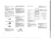
... not open or close to the timer. 6. Never dry discs with a soft, dry cloth. Thus, use of the TV. Programmed playback does not work. • Is the disc loaded properly? See page 14 pressed. peak) 2.0 V fixed DISCS Compact Disc format GENERAL CHARACTERISTICS Power Supply: Voltage and frequency is brought into a warm room Irom a cold area, such as close . intro scan Track number, time, music calendar, and engaged modes Headphones jack RC...
... not open or close to the timer. 6. Never dry discs with a soft, dry cloth. Thus, use of the TV. Programmed playback does not work. • Is the disc loaded properly? See page 14 pressed. peak) 2.0 V fixed DISCS Compact Disc format GENERAL CHARACTERISTICS Power Supply: Voltage and frequency is brought into a warm room Irom a cold area, such as close . intro scan Track number, time, music calendar, and engaged modes Headphones jack RC...

Service Manual
Page 9
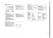
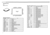
...PD connector(White) This denotes the serial number used for example, 56.5mA will be expressed as 565, but Oct. and Dec. C, 9 Label KSS-210A CCCOO O COO Lot No. Nov. day 00 month O year (last figure) quality control No. are expressed by mA, ...8226; The expressed unit is by alphabetical letters of the Components +Z-axis direction Ob'ect lens Actuator cover Slide base CICO425/335 CD Slide rack Soldered short circuit portion(Rear side) Label 1. quality control 10 1 10-1 OO O LD drive current 3. Serial number O O O O O 2. O O but Name • late...
...PD connector(White) This denotes the serial number used for example, 56.5mA will be expressed as 565, but Oct. and Dec. C, 9 Label KSS-210A CCCOO O COO Lot No. Nov. day 00 month O year (last figure) quality control No. are expressed by mA, ...8226; The expressed unit is by alphabetical letters of the Components +Z-axis direction Ob'ect lens Actuator cover Slide base CICO425/335 CD Slide rack Soldered short circuit portion(Rear side) Label 1. quality control 10 1 10-1 OO O LD drive current 3. Serial number O O O O O 2. O O but Name • late...
Service Manual
Page 10
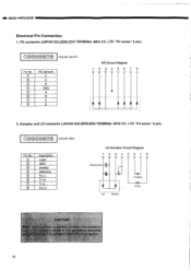
...; © CD 0 Description Laser GND monitor reference Fo (-) Tr (+) Tr (-) Fo (+) LD Actuator Circuit Diagram 12 3 4 567 8 Short-round r LD Monitor Tracking Focus CAUTION ck-up section, connect red connector or (white) of Pick-up section, and white D connector (red) of Pick-up section. 10 LTD "PH series" 8 pin) 00000000 COLOR: RED Pin No. DCD-425/335...
...; © CD 0 Description Laser GND monitor reference Fo (-) Tr (+) Tr (-) Fo (+) LD Actuator Circuit Diagram 12 3 4 567 8 Short-round r LD Monitor Tracking Focus CAUTION ck-up section, connect red connector or (white) of Pick-up section, and white D connector (red) of Pick-up section. 10 LTD "PH series" 8 pin) 00000000 COLOR: RED Pin No. DCD-425/335...

Service Manual
Page 11
... focus or tracking adjustment nor able to adjust the focus or tracking, it seems that there is impregnated with FROIL946P (by the Kanto Kasei Kogyo), never fail to supply the bushing with the circuit part of replacing the pick-up . 4. To open the short circuit, remove the soldering quickly with a soldering iron whose matal part is supplied to touch directly with...
... focus or tracking adjustment nor able to adjust the focus or tracking, it seems that there is impregnated with FROIL946P (by the Kanto Kasei Kogyo), never fail to supply the bushing with the circuit part of replacing the pick-up . 4. To open the short circuit, remove the soldering quickly with a soldering iron whose matal part is supplied to touch directly with...

Service Manual
Page 14
...) 3. Step. FRONT PANEL SIDE I VR103 (Focus offset) 3 O'clock VR101 O (Tracking offset) 3 O'clock 1. Adjustment method (1) Necessary equipment for adjustment 1. Oscillator (10 Hz - 10 kHz, 0 - 3 Vp-p) 4. Preset VR101 to 103. 2. Focus offset 2. Tracking gain VR102 (Tracking gain) 3 O'clock 14 Frequency counter (readable no less than 5 kHz) 5. Lissajous jig Input (Main unit) OSC INPUT Lissajous jig INPUT 22k GND OUTPUT 10k 4700P GND T 0.022µ 4700P 10k...
...) 3. Step. FRONT PANEL SIDE I VR103 (Focus offset) 3 O'clock VR101 O (Tracking offset) 3 O'clock 1. Adjustment method (1) Necessary equipment for adjustment 1. Oscillator (10 Hz - 10 kHz, 0 - 3 Vp-p) 4. Preset VR101 to 103. 2. Focus offset 2. Tracking gain VR102 (Tracking gain) 3 O'clock 14 Frequency counter (readable no less than 5 kHz) 5. Lissajous jig Input (Main unit) OSC INPUT Lissajous jig INPUT 22k GND OUTPUT 10k 4700P GND T 0.022µ 4700P 10k...

Service Manual
Page 15
... a frequency 1,100 Hz, output 5.0 Vp-p. 9. Insert the disc and set the unit in play mode. 10. DC 0V 0V ±0.05V 2. Connect an oscilloscope to TP3 (FEO) and TP5 (GND). 2. Connect OUTPUT terminal of Lissajous jig and TP1 (TEO). 3. Tracking offset Adjustment 1. Focus offset Adjustment 1. Connect an oscilloscope to TP1 (TEO) and TP5 (GND). 2.Insert the disc and set the unit in play mode. 3.Set VR102 fully counterclockwise. 4.Adjust...
... a frequency 1,100 Hz, output 5.0 Vp-p. 9. Insert the disc and set the unit in play mode. 10. DC 0V 0V ±0.05V 2. Connect an oscilloscope to TP3 (FEO) and TP5 (GND). 2. Connect OUTPUT terminal of Lissajous jig and TP1 (TEO). 3. Tracking offset Adjustment 1. Focus offset Adjustment 1. Connect an oscilloscope to TP1 (TEO) and TP5 (GND). 2.Insert the disc and set the unit in play mode. 3.Set VR102 fully counterclockwise. 4.Adjust...
Service Manual
Page 16
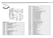
... Function Pin No. Input signal from A/D converter. - Connect to GND). L Key return input signal when scanning key by FDP segment signal. Not used (Open). CLOSE output signal for system clock oscillation. Laser control output signal. - X'tal connecting terminal for CD mechanism drive. O - Segment signal output terminal for FDP. Segment signal output terminal for FDP. O - Segment signal output terminal for FOP. Segment signal output terminal for FDP. O - O - Not used (Open). - Not used (Open). - O - O - O - Timing...
... Function Pin No. Input signal from A/D converter. - Connect to GND). L Key return input signal when scanning key by FDP segment signal. Not used (Open). CLOSE output signal for system clock oscillation. Laser control output signal. - X'tal connecting terminal for CD mechanism drive. O - Segment signal output terminal for FDP. Segment signal output terminal for FDP. O - Segment signal output terminal for FOP. Segment signal output terminal for FDP. O - O - Not used (Open). - Not used (Open). - O - O - O - Timing...
Service Manual
Page 17
... or 33.8688MHz. 0 X'tal oscillation circuit output of track jump number. 0 Serial data output to SSP. 0 Serial data latch output to CPU. I VCO control voltage input for analog EFM PLL. L: Serial output, H: Parallel output. 0 D/A Interface for aperture compensation. I Audio data output mode shifting input. I EFM signal input. PSSL=0 for GTOP output. 0 At PSSL=1 for DA1 output; SENS output. Resets at L. 0 Digital-out output terminal. 0 When emphasized playback disc, output H; Latches serial data at falling. PSSL=0 for MNT1...
... or 33.8688MHz. 0 X'tal oscillation circuit output of track jump number. 0 Serial data output to SSP. 0 Serial data latch output to CPU. I VCO control voltage input for analog EFM PLL. L: Serial output, H: Parallel output. 0 D/A Interface for aperture compensation. I Audio data output mode shifting input. I EFM signal input. PSSL=0 for GTOP output. 0 At PSSL=1 for DA1 output; SENS output. Resets at L. 0 Digital-out output terminal. 0 When emphasized playback disc, output H; Latches serial data at falling. PSSL=0 for MNT1...
Service Manual
Page 18
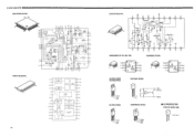
Input 2 A 7 B Output 8 A+Input 3 B 6 B- Input 8 V 4 -B 5 B + Input • A Output A- Input 2 A A + Input 3 B V 4 8 V 7 B Output 6 B- EEO FL8 FS3 FGD VC 0 PCM1712U (IC301) 14 28 0 LRCIN 1 DIN 9O4161 3 CLKO 4 XTI 5 XTO 6 DGND VDU 8 Vcc2R 9 ACND2R 10 EXTIR 11 EXT2R YOUTR 1 AGND1 14, INPUT INTERFACE TIMING CONTROL 5-LEVEL DAC RIGHT ML/DSD DIGITAL FILTER MODE CONTROL MC/DM2 6 C/DM1 5 MUTE NOISE SHAPER 5-LEVEL DAC LEFT LOW-PASS FILTER LEFT CMOS AMP LEFT 4 MODE CKSL DGND...
Input 2 A 7 B Output 8 A+Input 3 B 6 B- Input 8 V 4 -B 5 B + Input • A Output A- Input 2 A A + Input 3 B V 4 8 V 7 B Output 6 B- EEO FL8 FS3 FGD VC 0 PCM1712U (IC301) 14 28 0 LRCIN 1 DIN 9O4161 3 CLKO 4 XTI 5 XTO 6 DGND VDU 8 Vcc2R 9 ACND2R 10 EXTIR 11 EXT2R YOUTR 1 AGND1 14, INPUT INTERFACE TIMING CONTROL 5-LEVEL DAC RIGHT ML/DSD DIGITAL FILTER MODE CONTROL MC/DM2 6 C/DM1 5 MUTE NOISE SHAPER 5-LEVEL DAC LEFT LOW-PASS FILTER LEFT CMOS AMP LEFT 4 MODE CKSL DGND...

Service Manual
Page 21
... OUT 2 OND IN 0502 caw 3 OUT 2 Ole I .42 30 20 L_ o 2,g a i&A, POWER UNIT O 1F o S= 8 BK CP503 4=2 CP504 8K F2 F FLT MUTE A.580 13.0ND Wii ..., ,. ., 05 0. PRINTED WIRING BOARD 1 2 3 4 5 I 6 1 7 I ?4;•,=7,M6I•ACIN2U1NI0T9, 114 'L..) ONO. XRST ISC°Rtl-a4•24 .I FRONT UN IT ,rt E 5856 11 PLAY/PAUSE jia. $857 : SEARCH...REPEAT 5853 INTRO 9854 r,,J I SKIP - . _. ji 5862 CLEAR Y 585 A -EDIT to $86; it Plolzatil: GNO-, : MUTE 0503":.1 10505 3 OUT IN 5.4D cszl tO - 5V-• O cs, f ttj . CIn t 5860 STOP V -25 5858 OPEN...
... OUT 2 OND IN 0502 caw 3 OUT 2 Ole I .42 30 20 L_ o 2,g a i&A, POWER UNIT O 1F o S= 8 BK CP503 4=2 CP504 8K F2 F FLT MUTE A.580 13.0ND Wii ..., ,. ., 05 0. PRINTED WIRING BOARD 1 2 3 4 5 I 6 1 7 I ?4;•,=7,M6I•ACIN2U1NI0T9, 114 'L..) ONO. XRST ISC°Rtl-a4•24 .I FRONT UN IT ,rt E 5856 11 PLAY/PAUSE jia. $857 : SEARCH...REPEAT 5853 INTRO 9854 r,,J I SKIP - . _. ji 5862 CLEAR Y 585 A -EDIT to $86; it Plolzatil: GNO-, : MUTE 0503":.1 10505 3 OUT IN 5.4D cszl tO - 5V-• O cs, f ttj . CIn t 5860 STOP V -25 5858 OPEN...
Service Manual
Page 22
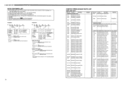
...wire forming * Capacity (electrolyte only) 2_2 2 t I " (i) to the Schematic Diagram for supplying, or in the P. No. ■ DCO-425/335 NOTE FOR PARTS LIST • Part indicated with the mark "0" are not always in stock and possibly to take a long period of time for those parts.) WARNING: Parts marked with the mark "*" is included after effective number. 2-digit effective number...carbon film t5% 1/4W and chip type resistor) VR101,102 960 0057 700 Semi fixed 10kohm-B VR103 DCD 2150 408 Semi fixed 4.7kohm-B CAPACITORS GROUP (Not included ceramic ch p type capacitor) C101 254 4254 ...
...wire forming * Capacity (electrolyte only) 2_2 2 t I " (i) to the Schematic Diagram for supplying, or in the P. No. ■ DCO-425/335 NOTE FOR PARTS LIST • Part indicated with the mark "0" are not always in stock and possibly to take a long period of time for those parts.) WARNING: Parts marked with the mark "*" is included after effective number. 2-digit effective number...carbon film t5% 1/4W and chip type resistor) VR101,102 960 0057 700 Semi fixed 10kohm-B VR103 DCD 2150 408 Semi fixed 4.7kohm-B CAPACITORS GROUP (Not included ceramic ch p type capacitor) C101 254 4254 ...
Service Manual
Page 26
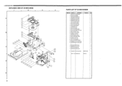
... 322 DC motor 16 960 0041 703 Leaf switch 17 960 0045 110 5P wire 18 DCD 2150 303 Feed frame 19 DCD 2150 309 Switch holder 20 960 0045 107 6P wire 21 DCD 2150 312 Insulator 22 DCD 2150 330 Rubber stopper 23 960 0045 217 SH connector Ass'y 24 960 0059 203 SH connector... Disc damper 5 960 0059 504 Guide frame 6 960 0059 407 Mecha base 7 DCD 2150 316 Rack spring 8 DCD 2150 308 Load gear 9 DCD 2150 305 Center gear 10 DCD 2150 306 Pully gear 11 960 0059 300 Tray 12 DCD 2150 314 Belt 13 DCD 2150 310 Motor pulley 14 DCD 2150 323 Motor P.W.B. Part No. I 000425/335 EXPLODED VIEW OF CD...
... 322 DC motor 16 960 0041 703 Leaf switch 17 960 0045 110 5P wire 18 DCD 2150 303 Feed frame 19 DCD 2150 309 Switch holder 20 960 0045 107 6P wire 21 DCD 2150 312 Insulator 22 DCD 2150 330 Rubber stopper 23 960 0045 217 SH connector Ass'y 24 960 0059 203 SH connector... Disc damper 5 960 0059 504 Guide frame 6 960 0059 407 Mecha base 7 DCD 2150 316 Rack spring 8 DCD 2150 308 Load gear 9 DCD 2150 305 Center gear 10 DCD 2150 306 Pully gear 11 960 0059 300 Tray 12 DCD 2150 314 Belt 13 DCD 2150 310 Motor pulley 14 DCD 2150 323 Motor P.W.B. Part No. I 000425/335 EXPLODED VIEW OF CD...
Service Manual
Page 31
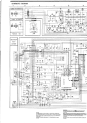
...line to chassis resistance check. Use ONLY replacement parts recommended by the manufacturer. WARNING: DO NOT return the unit to the customer, make sure you make either of the power cord...C125 0.047 0202 0.22/30 • R201 100K Fa 1 CD 0.0 WM= a AVDO CLTV AVSS F3LI FILO VOCE VP03 ?C a10...CHANGE WITHOUT PRIOR NOTICE. K*2100 3 9 1 !DOA YOUR 1ED 101* OLD SI THE MOTOR aD • 0104 100/10 0107 0.001 C105 0.001 • 0101 R. CAUTION: Before returning the unit to the customer until the problem is defective. P=MICRO-MICRO FARAD EACH VOLTAGE AND CURRENT ARE MEASURED AT NO SIGNAL INPUT...
...line to chassis resistance check. Use ONLY replacement parts recommended by the manufacturer. WARNING: DO NOT return the unit to the customer, make sure you make either of the power cord...C125 0.047 0202 0.22/30 • R201 100K Fa 1 CD 0.0 WM= a AVDO CLTV AVSS F3LI FILO VOCE VP03 ?C a10...CHANGE WITHOUT PRIOR NOTICE. K*2100 3 9 1 !DOA YOUR 1ED 101* OLD SI THE MOTOR aD • 0104 100/10 0107 0.001 C105 0.001 • 0101 R. CAUTION: Before returning the unit to the customer until the problem is defective. P=MICRO-MICRO FARAD EACH VOLTAGE AND CURRENT ARE MEASURED AT NO SIGNAL INPUT...

