

Literature/Product Sheet
Page 1
... recordings in its ability to 7 kHz with Pro Logic). Each channel is equipped with the DTS-ES (true discrete) 6.1 decoder, developed by DENON to provide dramatically improved surround sound panoramic reproduction and superior surround sound localization. s Featuring DTS-ES Discrete 6.1 Decoding The AVR-2802 is rated at a higher rank than 0.05% THD. The Dolby...
... recordings in its ability to 7 kHz with Pro Logic). Each channel is equipped with the DTS-ES (true discrete) 6.1 decoder, developed by DENON to provide dramatically improved surround sound panoramic reproduction and superior surround sound localization. s Featuring DTS-ES Discrete 6.1 Decoding The AVR-2802 is rated at a higher rank than 0.05% THD. The Dolby...
Literature/Product Sheet
Page 2
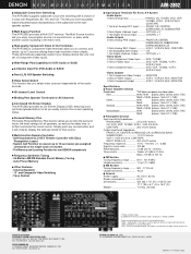
... you select video sources independently of a button • Pre-Memory and Learning Function for All Channels s Icon-based On-Screen Display The AVR-2802 provides an On-Screen Display (OSD) featuring icons (pictorial representations) to let you to 10... 416 (D) mm 17.1" (W) x 6.7" (H) x 16.4" (D) Weight 11.5 kg, 25.4 lbs DENON ELECTRONICS DIVISION OF DENON CORPORATION (USA) 19 CHAPIN ROAD, P.O. s High-quality Component Video In/Out Terminals The AVR-2802's Component Video terminals allow you more accurately match the performance characteristics of Digital Theater System, Inc. s ...
... you select video sources independently of a button • Pre-Memory and Learning Function for All Channels s Icon-based On-Screen Display The AVR-2802 provides an On-Screen Display (OSD) featuring icons (pictorial representations) to let you to 10... 416 (D) mm 17.1" (W) x 6.7" (H) x 16.4" (D) Weight 11.5 kg, 25.4 lbs DENON ELECTRONICS DIVISION OF DENON CORPORATION (USA) 19 CHAPIN ROAD, P.O. s High-quality Component Video In/Out Terminals The AVR-2802's Component Video terminals allow you more accurately match the performance characteristics of Digital Theater System, Inc. s ...

Owners Manual
Page 1
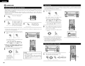
...PAGINA 218 SIDA 219 ~ SIDA 254 AV SURROUND RECEIVER AVR-2802 OPERATING INSTRUCTIONS BEDIENUNGSANLEITUNG MODE D'EMPLOI ISTRUZIONI PER L'USO INSTRUCCIONES DE OPERACION GEBRUIKSAANWIJZING BRUKSANVISNING B PRECISION AUDIO COMPONENT / AV SURROUND RECEIVER AVR-2802 FUNCTION REMOTE SENSOR STAND BY AUTO SIGNAL DIGITAL SURROUND BACK...VCR-1 CD 7 8 VCR-2/V.AUX +10 0 RC-904 LEARNED/TX POWER OFF ON / SOURCE TUNER 3 SHIFT PHONO 6 CDR / TAPE 9 CHANNEL TV/VCR A / B VOLUME DISC SKIP+ SURR.SP DOLBY / DTS SURROUND DIRECT DSP SIMULATION 5CH / 6CH STEREO INPUT MODE ANALOG STEREO EXT.IN ...
...PAGINA 218 SIDA 219 ~ SIDA 254 AV SURROUND RECEIVER AVR-2802 OPERATING INSTRUCTIONS BEDIENUNGSANLEITUNG MODE D'EMPLOI ISTRUZIONI PER L'USO INSTRUCCIONES DE OPERACION GEBRUIKSAANWIJZING BRUKSANVISNING B PRECISION AUDIO COMPONENT / AV SURROUND RECEIVER AVR-2802 FUNCTION REMOTE SENSOR STAND BY AUTO SIGNAL DIGITAL SURROUND BACK...VCR-1 CD 7 8 VCR-2/V.AUX +10 0 RC-904 LEARNED/TX POWER OFF ON / SOURCE TUNER 3 SHIFT PHONO 6 CDR / TAPE 9 CHANNEL TV/VCR A / B VOLUME DISC SKIP+ SURR.SP DOLBY / DTS SURROUND DIRECT DSP SIMULATION 5CH / 6CH STEREO INPUT MODE ANALOG STEREO EXT.IN ...

Owners Manual
Page 4
... transformer. • If humming or other component equipped with DTS Neo:6, a surround mode allowing 6.1-channel playback of component video outputs to audio equipment with MC cartridges directly. The AVR-2802 is at standby. NOTES: • This unit cannot be set of regular stereo sources. 6. ...unit's CD jacks using pin plug cords. 4 OUTPUT RL RL CD player DIGITAL AUDIO Connecting a turntable Connect the turntable's output cord to the AVR-2802's PHONO jacks, the L (left , right with digital input/output jacks B OUTPUT INPUT OPTICAL R LR L DIGITAL AUDIO R LRL INPUT ...
... transformer. • If humming or other component equipped with DTS Neo:6, a surround mode allowing 6.1-channel playback of component video outputs to audio equipment with MC cartridges directly. The AVR-2802 is at standby. NOTES: • This unit cannot be set of regular stereo sources. 6. ...unit's CD jacks using pin plug cords. 4 OUTPUT RL RL CD player DIGITAL AUDIO Connecting a turntable Connect the turntable's output cord to the AVR-2802's PHONO jacks, the L (left , right with digital input/output jacks B OUTPUT INPUT OPTICAL R LR L DIGITAL AUDIO R LRL INPUT ...

Owners Manual
Page 7
... back on speaker impedance L • The protector circuit may be used at the same time. Turn off the set is equipped with 6-channel analog output For instructions on operations using the external input (EXT. Doing so could result in contact with adjacent terminals, with > ). If...and the power supply indicator LED flashes. NOTE: NEVER touch the speaker terminals when the power is cut off the power and contact a DENON service center. Note on . When the protection circuit is activated, the speaker output is on . clockwise. For instructions on playback using ...
... back on speaker impedance L • The protector circuit may be used at the same time. Turn off the set is equipped with 6-channel analog output For instructions on operations using the external input (EXT. Doing so could result in contact with adjacent terminals, with > ). If...and the power supply indicator LED flashes. NOTE: NEVER touch the speaker terminals when the power is cut off the power and contact a DENON service center. Note on . When the protection circuit is activated, the speaker output is on . clockwise. For instructions on playback using ...

Owners Manual
Page 9
... ft) Center 3.6 m (12 ft) Sub Woofer 3.6 m (12 ft) Surround L & R 3.0 m (10 ft) Surround Back 3.0 m (10 ft) r Channel Level This adjusts the volume of the signals output from the speakers and subwoofer for optimizing the timing with the AVR-2802. (Nothing happens when they are received automatically and stored in "CONNECTIONS" (see pages 4 to 8), make...
... ft) Center 3.6 m (12 ft) Sub Woofer 3.6 m (12 ft) Surround L & R 3.0 m (10 ft) Surround Back 3.0 m (10 ft) r Channel Level This adjusts the volume of the signals output from the speakers and subwoofer for optimizing the timing with the AVR-2802. (Nothing happens when they are received automatically and stored in "CONNECTIONS" (see pages 4 to 8), make...

Owners Manual
Page 10
... If you do not have sufficient performance for reproducing bass sound below the frequency set for all the connections are input to the AVR-2802 from the different channels and the frequency response are installed. When this is set, bass sound with a frequency below ) signals. Yes/No Select "Yes... "2spkrs" is set for the Crossover Frequency mode and below the frequency set for the Crossover Frequency mode is connected to both the AVR-2802's S-Video and video monitor output jacks and signals are correct, then turn on TVs with small screens or low resolutions. • The...
... If you do not have sufficient performance for reproducing bass sound below the frequency set for all the connections are input to the AVR-2802 from the different channels and the frequency response are installed. When this is set, bass sound with a frequency below ) signals. Yes/No Select "Yes... "2spkrs" is set for the Crossover Frequency mode and below the frequency set for the Crossover Frequency mode is connected to both the AVR-2802's S-Video and video monitor output jacks and signals are correct, then turn on TVs with small screens or low resolutions. • The...

Owners Manual
Page 11
...Menu reappears. When using the surround back speaker(s). 3 ENTER Enter the setting. NON-MTRX: Sources are produced simultaneously from those channels and the subwoofer channel. NOTES: • The "SB CH Auto Flag Detect" setting screen is displayed when the surround back speaker(s) is/are...for the front speakers and "Yes" is set to "Large" are LFE signals (during Dolby Digital or DTS signal playback) and the channel specified as those channels. - Select the Frequency. 2 Select the "Subwoofer Mode". Setting q Auto Flag Detect Mode (AFDM) ON: This function only works ...
...Menu reappears. When using the surround back speaker(s). 3 ENTER Enter the setting. NON-MTRX: Sources are produced simultaneously from those channels and the subwoofer channel. NOTES: • The "SB CH Auto Flag Detect" setting screen is displayed when the surround back speaker(s) is/are...for the front speakers and "Yes" is set to "Large" are LFE signals (during Dolby Digital or DTS signal playback) and the channel specified as those channels. - Select the Frequency. 2 Select the "Subwoofer Mode". Setting q Auto Flag Detect Mode (AFDM) ON: This function only works ...

Owners Manual
Page 12
... Time". 7 ENTER Set the distance between the listening position and the speakers (L1 to L5 on the diagram at the right). The AVR-2802 automatically sets the optimum surround delay time for the listening room. 2 ENTER Switch to the measured distance. NOTE: • If the distance...: Measure the distances between the center speaker and listening position. ENGLISH Setting the delay time 6 • Input the distance between the different channels is equal. • From the listening position, listen to the test tones produced from the speakers to adjust the level. • The...
... Time". 7 ENTER Set the distance between the listening position and the speakers (L1 to L5 on the diagram at the right). The AVR-2802 automatically sets the optimum surround delay time for the listening room. 2 ENTER Switch to the measured distance. NOTE: • If the distance...: Measure the distances between the center speaker and listening position. ENGLISH Setting the delay time 6 • Input the distance between the different channels is equal. • From the listening position, listen to the test tones produced from the speakers to adjust the level. • The...

Owners Manual
Page 13
... the speaker for which you activate a particular surround sound mode, your preferred channel level adjustments for just that mode will be adjusted between a digital audio source (stereo - 2 channel) and a digital audio recorder. • Do not connect the output of the AVR-2802 for the different input sources. 1 At the System Setup Menu select "Digital...
... the speaker for which you activate a particular surround sound mode, your preferred channel level adjustments for just that mode will be adjusted between a digital audio source (stereo - 2 channel) and a digital audio recorder. • Do not connect the output of the AVR-2802 for the different input sources. 1 At the System Setup Menu select "Digital...

Owners Manual
Page 14
... this to turn the on-screen display (messages other than the menu screens) on or off . • On-screen display signals Signals input to the AVR-2802 VIDEO signal input jack (yellow) S-video signal input jack 1 E E 2 C E 3 E C 4 C C (C: Signal E: No signal) On-screen display signal output VIDEO MONITOR OUT video signal output ... SYSTEM SETUP TITLE At the System Setup Menu, press the SYSTEM SETUP button. NOTE: • If an FM station cannot be pressed at preset channels A1 to 8, B1 to 8, C1 to 8, D1 to 8 and E1 to 8. The display automatically switches to select "Yes".
... this to turn the on-screen display (messages other than the menu screens) on or off . • On-screen display signals Signals input to the AVR-2802 VIDEO signal input jack (yellow) S-video signal input jack 1 E E 2 C E 3 E C 4 C C (C: Signal E: No signal) On-screen display signal output VIDEO MONITOR OUT video signal output ... SYSTEM SETUP TITLE At the System Setup Menu, press the SYSTEM SETUP button. NOTE: • If an FM station cannot be pressed at preset channels A1 to 8, B1 to 8, C1 to 8, D1 to 8 and E1 to 8. The display automatically switches to select "Yes".

Owners Manual
Page 15
... do not plan to use it can be used to operate not only the AVR-2802 but this distance will be shorter if there are obstacles in the proper direction,... 5 VCR-1 CD 7 8 POWER OFF ON / SOURCE TUNER 3 SHIFT PHONO 6 CDR / TAPE 9 CHANNEL : Switch preset channel range : Preset channel up/down * For the tuner only, the following the "≈" and "√" marks in the battery ...components, some models of the different components before operating them as quickly as possible. Operating DENON audio components • Turn on Batteries • Use R6P/AA batteries in the remote...
... do not plan to use it can be used to operate not only the AVR-2802 but this distance will be shorter if there are obstacles in the proper direction,... 5 VCR-1 CD 7 8 POWER OFF ON / SOURCE TUNER 3 SHIFT PHONO 6 CDR / TAPE 9 CHANNEL : Switch preset channel range : Preset channel up/down * For the tuner only, the following the "≈" and "√" marks in the battery ...components, some models of the different components before operating them as quickly as possible. Operating DENON audio components • Turn on Batteries • Use R6P/AA batteries in the remote...

Owners Manual
Page 16
.../ SOURCE TUNER 3 SHIFT PHONO 6 CDR / TAPE 9 CHANNEL TV/VCR A / B 3,4 1 VOLUME DISC SKIP+ SPEAKER DOLBY / DTS SURROUND DIRECT DSP SIMULATION 5CH / 6CH STEREO INPUT MODE ANALOG STEREO EXT.IN MASTER VOL. Preset memory (Video component) • DENON and other components, repeat steps 2 to 4. • This...MD" Combinations of components can be CD MULTI registered (DVD, VDP, VCR or TV). . AUDIO TAPE CDR/MD CD MULTI MUTING AVR/AVC VIDEO TUNING DVD TV VDP VCR SYSTEM SETUP SURROUND PARAMETER BAND RDS MODE PTY MEMORY RT TITLE MENU/GUIDE CH SELECT ENTER SELECT...
.../ SOURCE TUNER 3 SHIFT PHONO 6 CDR / TAPE 9 CHANNEL TV/VCR A / B 3,4 1 VOLUME DISC SKIP+ SPEAKER DOLBY / DTS SURROUND DIRECT DSP SIMULATION 5CH / 6CH STEREO INPUT MODE ANALOG STEREO EXT.IN MASTER VOL. Preset memory (Video component) • DENON and other components, repeat steps 2 to 4. • This...MD" Combinations of components can be CD MULTI registered (DVD, VDP, VCR or TV). . AUDIO TAPE CDR/MD CD MULTI MUTING AVR/AVC VIDEO TUNING DVD TV VDP VCR SYSTEM SETUP SURROUND PARAMETER BAND RDS MODE PTY MEMORY RT TITLE MENU/GUIDE CH SELECT ENTER SELECT...

Owners Manual
Page 17
...TV/VCR : Switch between TV and VCR CHANNEL : Switch channel +, - 17 POWER : Power on Table 1 cannot be CD MULTI registered (DVD, VDP, VCR or TV). t - - p - - SHIFT (SHIFT) - - + CHANNEL (CHANNEL +) - - i (CD) TOSHIBA - IN) DENON C - - - - w (VDP...NEC A NEC B NEC C SHIFT (SHIFT) PHILIPS A PHILIPS B PHILIPS C + CHANNEL (CHANNEL +) CHANNEL - (CHANNEL -) A / B (A/B) RCA A RCA B - e (TUNER) MITSUBISHI A MITSUBISHI B r (TV/DBS) PANASONIC A PANASONIC B t JVC (VICTOR) - AVR/AVC VIDEO 2 TAPE CDR/MD Set the slide switch to the component to the ...
...TV/VCR : Switch between TV and VCR CHANNEL : Switch channel +, - 17 POWER : Power on Table 1 cannot be CD MULTI registered (DVD, VDP, VCR or TV). t - - p - - SHIFT (SHIFT) - - + CHANNEL (CHANNEL +) - - i (CD) TOSHIBA - IN) DENON C - - - - w (VDP...NEC A NEC B NEC C SHIFT (SHIFT) PHILIPS A PHILIPS B PHILIPS C + CHANNEL (CHANNEL +) CHANNEL - (CHANNEL -) A / B (A/B) RCA A RCA B - e (TUNER) MITSUBISHI A MITSUBISHI B r (TV/DBS) PANASONIC A PANASONIC B t JVC (VICTOR) - AVR/AVC VIDEO 2 TAPE CDR/MD Set the slide switch to the component to the ...

Owners Manual
Page 18
...the learn mode. ENGLISH Learning function • If your AV component is not a DENON product or it cannot be operated with the preset memory codesets, you can "teach" the AVR-2802's remote control to "learn" the codes from the remote control unit TV/DBS ... TV position. The two LEDs stop flashing and the learning mode is completed, press the USE/LEARN selector button again. To "learn " TV channels. Stored transmissions operation 1 10 Stored operation 2 Stored operation 3 Stored operation 4 Stored operation 5 Stored operation 6 Stored operation 7 Stored operation ...
...the learn mode. ENGLISH Learning function • If your AV component is not a DENON product or it cannot be operated with the preset memory codesets, you can "teach" the AVR-2802's remote control to "learn" the codes from the remote control unit TV/DBS ... TV position. The two LEDs stop flashing and the learning mode is completed, press the USE/LEARN selector button again. To "learn " TV channels. Stored transmissions operation 1 10 Stored operation 2 Stored operation 3 Stored operation 4 Stored operation 5 Stored operation 6 Stored operation 7 Stored operation ...

Owners Manual
Page 19
...SURROUND DIRECT DSP SIMULATION 5CH / 6CH STEREO INPUT MODE ANALOG STEREO EXT.IN MASTER VOL. AUDIO TAPE CDR/MD CD MULTI MUTING AVR/AVC VIDEO TUNING DVD TV VDP VCR SYSTEM SETUP SURROUND PARAMETER BAND RDS MODE PTY MEMORY RT TITLE MENU/GUIDE CH SELECT ENTER...1 2 TV/DBS 4 5 VCR-1 CD 7 8 VCR-2/V.AUX +10 0 RC-904 LEARNED/TX POWER OFF ON / SOURCE TUNER 3 SHIFT PHONO 6 CDR / TAPE 9 CHANNEL TV/VCR A / B 2 1,5 VOLUME DISC SKIP+ SPEAKER DOLBY / DTS SURROUND DIRECT DSP SIMULATION 5CH / 6CH STEREO INPUT MODE ANALOG STEREO EXT.IN MASTER VOL. flash. ...
...SURROUND DIRECT DSP SIMULATION 5CH / 6CH STEREO INPUT MODE ANALOG STEREO EXT.IN MASTER VOL. AUDIO TAPE CDR/MD CD MULTI MUTING AVR/AVC VIDEO TUNING DVD TV VDP VCR SYSTEM SETUP SURROUND PARAMETER BAND RDS MODE PTY MEMORY RT TITLE MENU/GUIDE CH SELECT ENTER...1 2 TV/DBS 4 5 VCR-1 CD 7 8 VCR-2/V.AUX +10 0 RC-904 LEARNED/TX POWER OFF ON / SOURCE TUNER 3 SHIFT PHONO 6 CDR / TAPE 9 CHANNEL TV/VCR A / B 2 1,5 VOLUME DISC SKIP+ SPEAKER DOLBY / DTS SURROUND DIRECT DSP SIMULATION 5CH / 6CH STEREO INPUT MODE ANALOG STEREO EXT.IN MASTER VOL. flash. ...

Owners Manual
Page 20
... 8 VCR-2/V.AUX +10 0 RC-904 LEARNED/TX POWER OFF ON / SOURCE TUNER 3 SHIFT PHONO 6 CDR / TAPE 9 CHANNEL TV/VCR A / B 3 4 2 VOLUME DISC SKIP+ SPEAKER DOLBY / DTS SURROUND DIRECT DSP SIMULATION 5CH / 6CH STEREO INPUT...MODE ANALOG STEREO EXT.IN MASTER VOL. AUDIO TAPE CDR/MD CD MULTI MUTING AVR/AVC VIDEO TUNING DVD TV VDP VCR SYSTEM SETUP SURROUND PARAMETER BAND MODE MEMORY ... mode to play in the memory. then operate the input function (Main unit) selector. 2802's surround decoder is output. w PCM (exclusive PCM signal playback mode) Decoding and playback are...
... 8 VCR-2/V.AUX +10 0 RC-904 LEARNED/TX POWER OFF ON / SOURCE TUNER 3 SHIFT PHONO 6 CDR / TAPE 9 CHANNEL TV/VCR A / B 3 4 2 VOLUME DISC SKIP+ SPEAKER DOLBY / DTS SURROUND DIRECT DSP SIMULATION 5CH / 6CH STEREO INPUT...MODE ANALOG STEREO EXT.IN MASTER VOL. AUDIO TAPE CDR/MD CD MULTI MUTING AVR/AVC VIDEO TUNING DVD TV VDP VCR SYSTEM SETUP SURROUND PARAMETER BAND MODE MEMORY ... mode to play in the memory. then operate the input function (Main unit) selector. 2802's surround decoder is output. w PCM (exclusive PCM signal playback mode) Decoding and playback are...

Owners Manual
Page 21
... input jacks. • The external input mode can be adjusted within the range of the EXT. In addition, signals cannot be output from channels not connected to switch the external input. When playing DTS-compatible sources, be sure to connect the source component to the digital input jacks (...) and connections are correct and whether the component's power is "18 dB - (Maximum value of 1 dB. AUDIO TAPE CDR/MD CD MULTI MUTING AVR/AVC VIDEO TUNING DVD TV VDP VCR SYSTEM SETUP SURROUND PARAMETER BAND MODE RDS PTY TITLE MENU/GUIDE CH SELECT ENTER SELECT 1 NOTES: • In...
... input jacks. • The external input mode can be adjusted within the range of the EXT. In addition, signals cannot be output from channels not connected to switch the external input. When playing DTS-compatible sources, be sure to connect the source component to the digital input jacks (...) and connections are correct and whether the component's power is "18 dB - (Maximum value of 1 dB. AUDIO TAPE CDR/MD CD MULTI MUTING AVR/AVC VIDEO TUNING DVD TV VDP VCR SYSTEM SETUP SURROUND PARAMETER BAND MODE RDS PTY TITLE MENU/GUIDE CH SELECT ENTER SELECT 1 NOTES: • In...

Owners Manual
Page 23
...2 TV/DBS 4 5 VCR-1 CD 7 8 VCR-2/V.AUX +10 0 RC-904 LEARNED/TX POWER OFF ON / SOURCE TUNER 3 SHIFT PHONO 6 CDR / TAPE 9 CHANNEL TV/VCR A / B 1 2 VOLUME DISC SKIP+ SPEAKER DOLBY / DTS SURROUND DIRECT DSP SIMULATION 5CH / 6CH STEREO INPUT MODE ANALOG STEREO EXT.IN MASTER VOL. The... Control unit) The remote control unit's MULTI button can be output using MULTI ZONE OUT) ANOTHER ROOM MAIN ROOM INTEGRATED AMPLIFIER B AVR-2802 MULTI SOURCE AUDIO signal cable SPEAKER cable * Refer to CONNECTIONS on which this unit and the playback devices are not output from the...
...2 TV/DBS 4 5 VCR-1 CD 7 8 VCR-2/V.AUX +10 0 RC-904 LEARNED/TX POWER OFF ON / SOURCE TUNER 3 SHIFT PHONO 6 CDR / TAPE 9 CHANNEL TV/VCR A / B 1 2 VOLUME DISC SKIP+ SPEAKER DOLBY / DTS SURROUND DIRECT DSP SIMULATION 5CH / 6CH STEREO INPUT MODE ANALOG STEREO EXT.IN MASTER VOL. The... Control unit) The remote control unit's MULTI button can be output using MULTI ZONE OUT) ANOTHER ROOM MAIN ROOM INTEGRATED AMPLIFIER B AVR-2802 MULTI SOURCE AUDIO signal cable SPEAKER cable * Refer to CONNECTIONS on which this unit and the playback devices are not output from the...
Owners Manual
Page 24
... the test tones is set to "SBR", "SBL". 2 Adjust the level of the front channels (FL, C and FR) or the rear channels (SL, SR and SB) together. AUDIO TAPE CDR/MD CD MULTI MUTING AVR/AVC VIDEO TUNING DVD TV VDP VCR SYSTEM SETUP SURROUND PARAMETER BAND RDS MODE PTY MEMORY... AUTO SIGNAL DIGITAL INPUT DIGITAL PCM VOLUME LEVEL (Main unit) (Remote control unit) The channel switches in the order shown below each time this is pressed. AUDIO TAPE CDR/MD CD MULTI MUTING AVR/AVC VIDEO TUNING DVD TV VDP VCR SYSTEM SETUP SURROUND PARAMETER BAND MODE MEMORY RDS PTY...
... the test tones is set to "SBR", "SBL". 2 Adjust the level of the front channels (FL, C and FR) or the rear channels (SL, SR and SB) together. AUDIO TAPE CDR/MD CD MULTI MUTING AVR/AVC VIDEO TUNING DVD TV VDP VCR SYSTEM SETUP SURROUND PARAMETER BAND RDS MODE PTY MEMORY... AUTO SIGNAL DIGITAL INPUT DIGITAL PCM VOLUME LEVEL (Main unit) (Remote control unit) The channel switches in the order shown below each time this is pressed. AUDIO TAPE CDR/MD CD MULTI MUTING AVR/AVC VIDEO TUNING DVD TV VDP VCR SYSTEM SETUP SURROUND PARAMETER BAND MODE MEMORY RDS PTY...


