

Literature/Product Sheet
Page 1
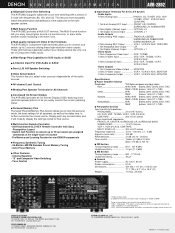
... devices, and all five, or six, speakers. A hallmark of Denon A/V component design, the equal power amplifier provides outstandingly accurate reproduction of motion picture soundtracks and multi-channel music programs. s Single-Channel Surround Back Power AMP for 6.1 Surround and 2-channel Pre-output for 7.1 Surround The AVR-2802 is equipped with a total of 6 power amps including one for...
... devices, and all five, or six, speakers. A hallmark of Denon A/V component design, the equal power amplifier provides outstandingly accurate reproduction of motion picture soundtracks and multi-channel music programs. s Single-Channel Surround Back Power AMP for 6.1 Surround and 2-channel Pre-output for 7.1 Surround The AVR-2802 is equipped with a total of 6 power amps including one for...
Literature/Product Sheet
Page 2
... 5.0 A Dimensions 434 (W) x 171 (H) x 416 (D) mm 17.1" (W) x 6.7" (H) x 16.4" (D) Weight 11.5 kg, 25.4 lbs DENON ELECTRONICS DIVISION OF DENON CORPORATION (USA) 19 CHAPIN ROAD, P.O. These terminals are trademarks of Dolby Laboratories Licensing Corporation. *"DTS", "DTS-ES Extended Surround" and "Neo:6" are... is displayed as the delay time, to the main speaker system. s All-channel Level Control s Binding Post Speaker Terminals for All Channels s Icon-based On-Screen Display The AVR-2802 provides an On-Screen Display (OSD) featuring icons (pictorial representations) to change ...
... 5.0 A Dimensions 434 (W) x 171 (H) x 416 (D) mm 17.1" (W) x 6.7" (H) x 16.4" (D) Weight 11.5 kg, 25.4 lbs DENON ELECTRONICS DIVISION OF DENON CORPORATION (USA) 19 CHAPIN ROAD, P.O. These terminals are trademarks of Dolby Laboratories Licensing Corporation. *"DTS", "DTS-ES Extended Surround" and "Neo:6" are... is displayed as the delay time, to the main speaker system. s All-channel Level Control s Binding Post Speaker Terminals for All Channels s Icon-based On-Screen Display The AVR-2802 provides an On-Screen Display (OSD) featuring icons (pictorial representations) to change ...

Owners Manual
Page 1
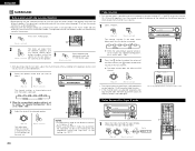
... VCR-1 CD 7 8 VCR-2/V.AUX +10 0 RC-904 LEARNED/TX POWER OFF ON / SOURCE TUNER 3 SHIFT PHONO 6 CDR / TAPE 9 CHANNEL TV/VCR A / B VOLUME DISC SKIP+ SURR.SP DOLBY / DTS SURROUND DIRECT DSP SIMULATION 5CH / 6CH STEREO INPUT MODE ANALOG STEREO EXT.IN...PAGINA 218 SIDA 219 ~ SIDA 254 AV SURROUND RECEIVER AVR-2802 OPERATING INSTRUCTIONS BEDIENUNGSANLEITUNG MODE D'EMPLOI ISTRUZIONI PER L'USO INSTRUCCIONES DE OPERACION GEBRUIKSAANWIJZING BRUKSANVISNING B PRECISION AUDIO COMPONENT / AV SURROUND RECEIVER AVR-2802 FUNCTION REMOTE SENSOR STAND BY AUTO SIGNAL DIGITAL SURROUND BACK...
... VCR-1 CD 7 8 VCR-2/V.AUX +10 0 RC-904 LEARNED/TX POWER OFF ON / SOURCE TUNER 3 SHIFT PHONO 6 CDR / TAPE 9 CHANNEL TV/VCR A / B VOLUME DISC SKIP+ SURR.SP DOLBY / DTS SURROUND DIRECT DSP SIMULATION 5CH / 6CH STEREO INPUT MODE ANALOG STEREO EXT.IN...PAGINA 218 SIDA 219 ~ SIDA 254 AV SURROUND RECEIVER AVR-2802 OPERATING INSTRUCTIONS BEDIENUNGSANLEITUNG MODE D'EMPLOI ISTRUZIONI PER L'USO INSTRUCCIONES DE OPERACION GEBRUIKSAANWIJZING BRUKSANVISNING B PRECISION AUDIO COMPONENT / AV SURROUND RECEIVER AVR-2802 FUNCTION REMOTE SENSOR STAND BY AUTO SIGNAL DIGITAL SURROUND BACK...

Owners Manual
Page 4
... Switching In addition to composite video and "S" video switching, the AVR-2802 provides 2 sets of component video (Y, PB/CB, PR/CR) inputs for the DVD and TV/DBS inputs, and one speaker, connect the speaker to 5.1 channels of component video outputs to this unit's CD jacks using pin ... for coaxial connections. • Use optical cables for North American DVD and DTV. 4. DTS-ES Extended Surround and DTS Neo:6 The AVR-2802 is generated by Digital Theater Systems Inc. Never use the AC OUTLET for playing multichannel audio signals that offers improvements over conventional Dolby Pro...
... Switching In addition to composite video and "S" video switching, the AVR-2802 provides 2 sets of component video (Y, PB/CB, PR/CR) inputs for the DVD and TV/DBS inputs, and one speaker, connect the speaker to 5.1 channels of component video outputs to this unit's CD jacks using pin ... for coaxial connections. • Use optical cables for North American DVD and DTV. 4. DTS-ES Extended Surround and DTS Neo:6 The AVR-2802 is generated by Digital Theater Systems Inc. Never use the AC OUTLET for playing multichannel audio signals that offers improvements over conventional Dolby Pro...

Owners Manual
Page 7
...used at the same time, since use as front and center speakers. • Speakers with 6-channel analog output For instructions on . If the protection circuit is cut off the power and contact a DENON service center. IN) jacks • These jacks are any faults with the wiring of front... components. Speaker Impedance • Speakers with an impedance of from an outboard decoder, or a component with a different type of multi-channel decoder, such as when the output of the power amplifier is inadvertently shortcircuited and a large current flows, when the temperature surrounding the unit...
...used at the same time, since use as front and center speakers. • Speakers with 6-channel analog output For instructions on . If the protection circuit is cut off the power and contact a DENON service center. IN) jacks • These jacks are any faults with the wiring of front... components. Speaker Impedance • Speakers with an impedance of from an outboard decoder, or a component with a different type of multi-channel decoder, such as when the output of the power amplifier is inadvertently shortcircuited and a large current flows, when the temperature surrounding the unit...

Owners Manual
Page 9
...components have been completed as described in "CONNECTIONS" (see pages 4 to 8), make the various settings described below on the monitor screen using the AVR-2802's on-screen display function. DVD TV/DBS CDR /TAPE VDP VCR-1 VCR-2 - Also use this to display the system setup menu. Front Sp... Channel select/enter button 10) Cursor buttons 10) ON SCREEN button 22) DVD SETUP button 17) STATUS button 22) Multi source button 23) NOTES: • The shaded buttons do not function with which the bass sound of the various speakers is for optimizing the timing with the AVR-2802....
...components have been completed as described in "CONNECTIONS" (see pages 4 to 8), make the various settings described below on the monitor screen using the AVR-2802's on-screen display function. DVD TV/DBS CDR /TAPE VDP VCR-1 VCR-2 - Also use this to display the system setup menu. Front Sp... Channel select/enter button 10) Cursor buttons 10) ON SCREEN button 22) DVD SETUP button 17) STATUS button 22) Multi source button 23) NOTES: • The shaded buttons do not function with which the bass sound of the various speakers is for optimizing the timing with the AVR-2802....

Owners Manual
Page 10
...monitor TVs, so it may be achieved even when "Small" is connected to both the AVR-2802's S-Video and video monitor output jacks and signals are input to the AVR-2802 from the different channels and the frequency response are adjusted automatically according to a level low enough so as possible...Frequency mode are connected and, if so, their front surfaces as flush with priority to the speaker's capacity for the surround back channel. When this when using speakers that have sufficient performance for reproducing bass sound below the frequency set for the Crossover Frequency mode....
...monitor TVs, so it may be achieved even when "Small" is connected to both the AVR-2802's S-Video and video monitor output jacks and signals are input to the AVR-2802 from the different channels and the frequency response are adjusted automatically according to a level low enough so as possible...Frequency mode are connected and, if so, their front surfaces as flush with priority to the speaker's capacity for the surround back channel. When this when using speakers that have sufficient performance for reproducing bass sound below the frequency set for the Crossover Frequency mode....

Owners Manual
Page 11
... CH Auto Flag Detect" setting screen is displayed when the surround back speaker(s) is/are produced simultaneously from those of the surround channel are played using the surround back speaker(s). NOTE: For ordinary speaker systems, we recommend setting the crossover frequency to "Large" are... Select the "Subwoofer Mode". Subwoofer mode - • When the "LFE+MAIN" playback mode is selected, the low frequency signal range of channels set to "Small" in the setup menu. The subwoofer mode setting is only valid when "Large" is set for frequencies near the crossover ...
... CH Auto Flag Detect" setting screen is displayed when the surround back speaker(s) is/are produced simultaneously from those of the surround channel are played using the surround back speaker(s). NOTE: For ordinary speaker systems, we recommend setting the crossover frequency to "Large" are... Select the "Subwoofer Mode". Subwoofer mode - • When the "LFE+MAIN" playback mode is selected, the low frequency signal range of channels set to "Small" in the setup menu. The subwoofer mode setting is only valid when "Large" is set for frequencies near the crossover ...

Owners Manual
Page 12
... ft) or less. If you set separately for "Default", the settings are reset to the Channel Level screen. 3 Select "Test Tone Mode". 12 Example: When "Meters" is selected Setting the channel level • Use this case, please relocate the blinking speaker(s) so that the playback level .... (For details, see page 24.) 1 At the System Setup Menu select "Channel Level". 2 ENTER Switch to the factory default values (see page 9). 3 Select the desired unit, meters or feet. The AVR-2802 automatically sets the optimum surround delay time for the listening room. 2 ENTER Switch ...
... ft) or less. If you set separately for "Default", the settings are reset to the Channel Level screen. 3 Select "Test Tone Mode". 12 Example: When "Meters" is selected Setting the channel level • Use this case, please relocate the blinking speaker(s) so that the playback level .... (For details, see page 24.) 1 At the System Setup Menu select "Channel Level". 2 ENTER Switch to the factory default values (see page 9). 3 Select the desired unit, meters or feet. The AVR-2802 automatically sets the optimum surround delay time for the listening room. 2 ENTER Switch ...

Owners Manual
Page 13
...is set to the same volume. Setting the Digital In Assignment • This setting assigns the digital input jacks of the AVR-2802 for adjusting channel levels within each of the test tones from which no digital input jacks are equipped with an optical digital output jack for ...natural balance. After you have completed the SYSTEM SETUP CHANNEL LEVEL adjustments, you want to select the speaker for each surround mode on the AVR-2802's rear panel are used. Check the instructions for the different input sources. 1 At the...
...is set to the same volume. Setting the Digital In Assignment • This setting assigns the digital input jacks of the AVR-2802 for adjusting channel levels within each of the test tones from which no digital input jacks are equipped with an optical digital output jack for ...natural balance. After you have completed the SYSTEM SETUP CHANNEL LEVEL adjustments, you want to select the speaker for each surround mode on the AVR-2802's rear panel are used. Check the instructions for the different input sources. 1 At the...

Owners Manual
Page 14
...1 SYSTEM SETUP TITLE At the System Setup Menu, press the SYSTEM SETUP button. NOTE: • If an FM station cannot be pressed at preset channels A1 to 8, B1 to 8, C1 to 8, D1 to 8 and E1 to 8. The System Setup Menu reappears. NOTES: • The on-... Preset Memory" screen appears. 3 14 Use the CURSOR button to screen. "Search" flashes on or off . • On-screen display signals Signals input to the AVR-2802 VIDEO signal input jack (yellow) S-video signal input jack 1 E E 2 C E 3 E C 4 C C (C: Signal E: No signal) On-screen display signal output VIDEO MONITOR ...
...1 SYSTEM SETUP TITLE At the System Setup Menu, press the SYSTEM SETUP button. NOTE: • If an FM station cannot be pressed at preset channels A1 to 8, B1 to 8, C1 to 8, D1 to 8 and E1 to 8. The System Setup Menu reappears. NOTES: • The on-... Preset Memory" screen appears. 3 14 Use the CURSOR button to screen. "Search" flashes on or off . • On-screen display signals Signals input to the AVR-2802 VIDEO signal input jack (yellow) S-video signal input jack 1 E E 2 C E 3 E C 4 C C (C: Signal E: No signal) On-screen display signal output VIDEO MONITOR ...

Owners Manual
Page 15
...flames. • Remove the batteries from the main unit, but other remote control compatible DENON components as well. w Set three R6P/AA batteries in the battery compartment in permanent ...-1 CD 7 8 POWER OFF ON / SOURCE TUNER 3 SHIFT PHONO 6 CDR / TAPE 9 CHANNEL : Switch preset channel range : Preset channel up to 30 degrees with a wide range of infrared controlled components, some models of approximately 7 ... set . (The included battery is compatible with respect to operate not only the AVR-2802 but this remote control is only for an extended period of time. •...
...flames. • Remove the batteries from the main unit, but other remote control compatible DENON components as well. w Set three R6P/AA batteries in the battery compartment in permanent ...-1 CD 7 8 POWER OFF ON / SOURCE TUNER 3 SHIFT PHONO 6 CDR / TAPE 9 CHANNEL : Switch preset channel range : Preset channel up to 30 degrees with a wide range of infrared controlled components, some models of approximately 7 ... set . (The included battery is compatible with respect to operate not only the AVR-2802 but this remote control is only for an extended period of time. •...

Owners Manual
Page 16
... 2 TV/DBS 4 5 VCR-1 CD 7 8 VCR-2/V.AUX +10 0 RC-904 LEARNED/TX POWER OFF ON / SOURCE TUNER 3 SHIFT PHONO 6 CDR / TAPE 9 CHANNEL TV/VCR A / B 3,4 1 VOLUME DISC SKIP+ SPEAKER DOLBY / DTS SURROUND DIRECT DSP SIMULATION 5CH / 6CH STEREO INPUT MODE ANALOG STEREO EXT.IN MASTER VOL. Preset ...page 18) to "CDR/MD". In this case use the learning function (see page 19. IN) (POWER) ON/SOURCE DENON CDR A DENON CDR B DENON MD Preset codes set . AVR/AVC VIDEO 2 TAPE CDR/MD Set the slide switch to store the remote control signals. • For instructions on clearing...
... 2 TV/DBS 4 5 VCR-1 CD 7 8 VCR-2/V.AUX +10 0 RC-904 LEARNED/TX POWER OFF ON / SOURCE TUNER 3 SHIFT PHONO 6 CDR / TAPE 9 CHANNEL TV/VCR A / B 3,4 1 VOLUME DISC SKIP+ SPEAKER DOLBY / DTS SURROUND DIRECT DSP SIMULATION 5CH / 6CH STEREO INPUT MODE ANALOG STEREO EXT.IN MASTER VOL. Preset ...page 18) to "CDR/MD". In this case use the learning function (see page 19. IN) (POWER) ON/SOURCE DENON CDR A DENON CDR B DENON MD Preset codes set . AVR/AVC VIDEO 2 TAPE CDR/MD Set the slide switch to store the remote control signals. • For instructions on clearing...

Owners Manual
Page 17
...- - y (PHONO) SONY - i (CD) TOSHIBA - o (CDR/TAPE) - - (VCR/V. AUX) - - SHIFT (SHIFT) - - + CHANNEL (CHANNEL +) - - CHANNEL - (CHANNEL -) - - A / B (A/B) - - r (TV/DBS) PANASONIC - t - - o (CDR/TAPE) - - (VCR/V. AUX) - - p - - EXT.IN (EXT. IN) DENON C - - - - SONY C "VCR" A q (DVD) B DIRECT STEREO EXT.IN (DIRECT) (STEREO) (EXT. e (TUNER) MITSUBISHI A MITSUBISHI...STEREO EXT.IN MASTER VOL. AUDIO TAPE CDR/MD CD MULTI MUTING AVR/AVC VIDEO TUNING DVD TV VDP VCR SYSTEM SETUP SURROUND PARAMETER BAND...
...- - y (PHONO) SONY - i (CD) TOSHIBA - o (CDR/TAPE) - - (VCR/V. AUX) - - SHIFT (SHIFT) - - + CHANNEL (CHANNEL +) - - CHANNEL - (CHANNEL -) - - A / B (A/B) - - r (TV/DBS) PANASONIC - t - - o (CDR/TAPE) - - (VCR/V. AUX) - - p - - EXT.IN (EXT. IN) DENON C - - - - SONY C "VCR" A q (DVD) B DIRECT STEREO EXT.IN (DIRECT) (STEREO) (EXT. e (TUNER) MITSUBISHI A MITSUBISHI...STEREO EXT.IN MASTER VOL. AUDIO TAPE CDR/MD CD MULTI MUTING AVR/AVC VIDEO TUNING DVD TV VDP VCR SYSTEM SETUP SURROUND PARAMETER BAND...

Owners Manual
Page 18
.../DBS 4 5 VCR-1 CD 7 8 VCR-2/V.AUX +10 0 RC-904 LEARNED/TX POWER OFF ON / SOURCE TUNER 3 SHIFT PHONO 6 CDR / TAPE 9 CHANNEL TV/VCR A / B 1 VOLUME DISC SKIP+ SPEAKER DOLBY / DTS SURROUND DIRECT DSP SIMULATION 5CH / 6CH STEREO INPUT MODE ANALOG STEREO EXT.IN MASTER VOL. ... steps 2 to 6. ENGLISH Learning function • If your AV component is not a DENON product or it cannot be operated with the preset memory codesets, you can "teach" the AVR-2802's remote control to "learn" the codes from the remote control unit TV/DBS approximately once...
.../DBS 4 5 VCR-1 CD 7 8 VCR-2/V.AUX +10 0 RC-904 LEARNED/TX POWER OFF ON / SOURCE TUNER 3 SHIFT PHONO 6 CDR / TAPE 9 CHANNEL TV/VCR A / B 1 VOLUME DISC SKIP+ SPEAKER DOLBY / DTS SURROUND DIRECT DSP SIMULATION 5CH / 6CH STEREO INPUT MODE ANALOG STEREO EXT.IN MASTER VOL. ... steps 2 to 6. ENGLISH Learning function • If your AV component is not a DENON product or it cannot be operated with the preset memory codesets, you can "teach" the AVR-2802's remote control to "learn" the codes from the remote control unit TV/DBS approximately once...

Owners Manual
Page 19
...SURROUND DIRECT DSP SIMULATION 5CH / 6CH STEREO INPUT MODE ANALOG STEREO EXT.IN MASTER VOL. AUDIO TAPE CDR/MD CD MULTI MUTING AVR/AVC VIDEO TUNING DVD TV VDP VCR SYSTEM SETUP SURROUND PARAMETER BAND RDS MODE PTY MEMORY RT TITLE MENU/GUIDE CH SELECT ENTER ... 2 TV/DBS 4 5 VCR-1 CD 7 8 VCR-2/V.AUX +10 0 RC-904 LEARNED/TX POWER OFF ON / SOURCE TUNER 3 SHIFT PHONO 6 CDR / TAPE 9 CHANNEL TV/VCR A / B 2 1,5 VOLUME DISC SKIP+ SPEAKER DOLBY / DTS SURROUND DIRECT DSP SIMULATION 5CH / 6CH STEREO INPUT MODE ANALOG STEREO EXT.IN MASTER VOL. flash. ...
...SURROUND DIRECT DSP SIMULATION 5CH / 6CH STEREO INPUT MODE ANALOG STEREO EXT.IN MASTER VOL. AUDIO TAPE CDR/MD CD MULTI MUTING AVR/AVC VIDEO TUNING DVD TV VDP VCR SYSTEM SETUP SURROUND PARAMETER BAND RDS MODE PTY MEMORY RT TITLE MENU/GUIDE CH SELECT ENTER ... 2 TV/DBS 4 5 VCR-1 CD 7 8 VCR-2/V.AUX +10 0 RC-904 LEARNED/TX POWER OFF ON / SOURCE TUNER 3 SHIFT PHONO 6 CDR / TAPE 9 CHANNEL TV/VCR A / B 2 1,5 VOLUME DISC SKIP+ SPEAKER DOLBY / DTS SURROUND DIRECT DSP SIMULATION 5CH / 6CH STEREO INPUT MODE ANALOG STEREO EXT.IN MASTER VOL. flash. ...

Owners Manual
Page 20
...8 VCR-2/V.AUX +10 0 RC-904 LEARNED/TX POWER OFF ON / SOURCE TUNER 3 SHIFT PHONO 6 CDR / TAPE 9 CHANNEL TV/VCR A / B 3 4 2 VOLUME DISC SKIP+ SPEAKER DOLBY / DTS SURROUND DIRECT DSP SIMULATION 5CH / 6CH STEREO...8226; Selecting the external input (EXT. AUDIO TAPE CDR/MD CD MULTI MUTING AVR/AVC VIDEO TUNING DVD TV VDP VCR SYSTEM SETUP SURROUND PARAMETER BAND RDS MODE PTY...passing through the surround circuitry. then operate the input function (Main unit) selector. 2802's surround decoder is being input to the AUDIO position. (only when operating with DTS...
...8 VCR-2/V.AUX +10 0 RC-904 LEARNED/TX POWER OFF ON / SOURCE TUNER 3 SHIFT PHONO 6 CDR / TAPE 9 CHANNEL TV/VCR A / B 3 4 2 VOLUME DISC SKIP+ SPEAKER DOLBY / DTS SURROUND DIRECT DSP SIMULATION 5CH / 6CH STEREO...8226; Selecting the external input (EXT. AUDIO TAPE CDR/MD CD MULTI MUTING AVR/AVC VIDEO TUNING DVD TV VDP VCR SYSTEM SETUP SURROUND PARAMETER BAND RDS MODE PTY...passing through the surround circuitry. then operate the input function (Main unit) selector. 2802's surround decoder is being input to the AUDIO position. (only when operating with DTS...

Owners Manual
Page 21
... signal is selected, the input signals connected to 18 dB, in the "ANALOG" or "PCM" mode. AUDIO TAPE CDR/MD CD MULTI MUTING AVR/AVC VIDEO TUNING DVD TV VDP VCR SYSTEM SETUP SURROUND PARAMETER BAND MODE RDS PTY TITLE MENU/GUIDE CH SELECT ENTER SELECT 1 NOTES: • ... DIGITAL PCM VOLUME LEVEL (Main unit) (Remote control unit) Once this case the maximum volume adjustment range is "18 dB - (Maximum value of channel level)".) Input mode when playing DTS sources • Noise will light when playing CD-ROMs containing data other than audio signals, but no sound will...
... signal is selected, the input signals connected to 18 dB, in the "ANALOG" or "PCM" mode. AUDIO TAPE CDR/MD CD MULTI MUTING AVR/AVC VIDEO TUNING DVD TV VDP VCR SYSTEM SETUP SURROUND PARAMETER BAND MODE RDS PTY TITLE MENU/GUIDE CH SELECT ENTER SELECT 1 NOTES: • ... DIGITAL PCM VOLUME LEVEL (Main unit) (Remote control unit) Once this case the maximum volume adjustment range is "18 dB - (Maximum value of channel level)".) Input mode when playing DTS sources • Noise will light when playing CD-ROMs containing data other than audio signals, but no sound will...

Owners Manual
Page 23
.../DBS 4 5 VCR-1 CD 7 8 VCR-2/V.AUX +10 0 RC-904 LEARNED/TX POWER OFF ON / SOURCE TUNER 3 SHIFT PHONO 6 CDR / TAPE 9 CHANNEL TV/VCR A / B 1 2 VOLUME DISC SKIP+ SPEAKER DOLBY / DTS SURROUND DIRECT DSP SIMULATION 5CH / 6CH STEREO INPUT MODE ANALOG STEREO EXT.IN MASTER VOL... of the source selected in other rooms, different sources can be output using MULTI ZONE OUT) ANOTHER ROOM MAIN ROOM INTEGRATED AMPLIFIER B AVR-2802 MULTI SOURCE AUDIO signal cable SPEAKER cable * Refer to "AUDIO" and "MULTI". FUNCTION (Main unit) 1 Display 2 REC PHONO ...
.../DBS 4 5 VCR-1 CD 7 8 VCR-2/V.AUX +10 0 RC-904 LEARNED/TX POWER OFF ON / SOURCE TUNER 3 SHIFT PHONO 6 CDR / TAPE 9 CHANNEL TV/VCR A / B 1 2 VOLUME DISC SKIP+ SPEAKER DOLBY / DTS SURROUND DIRECT DSP SIMULATION 5CH / 6CH STEREO INPUT MODE ANALOG STEREO EXT.IN MASTER VOL... of the source selected in other rooms, different sources can be output using MULTI ZONE OUT) ANOTHER ROOM MAIN ROOM INTEGRATED AMPLIFIER B AVR-2802 MULTI SOURCE AUDIO signal cable SPEAKER cable * Refer to "AUDIO" and "MULTI". FUNCTION (Main unit) 1 Display 2 REC PHONO ...
Owners Manual
Page 24
... VDP 1 2 TV/DBS 4 5 VCR-1 CD 7 8 VCR-2/V.AUX +10 0 RC-904 LEARNED/TX POWER OFF ON / SOURCE TUNER 3 SHIFT PHONO 6 CDR / TAPE 9 CHANNEL TV/VCR A / B 1 VOLUME DISC SKIP+ SPEAKER DOLBY / DTS SURROUND DIRECT DSP SIMULATION 5CH / 6CH STEREO INPUT MODE ANALOG STEREO EXT.IN MASTER VOL. B VOLUME LEVEL...to -12 dB. • When using the test tones is pressed. The fader function does not affect the SW channel. AUDIO TAPE CDR/MD CD MULTI MUTING AVR/AVC VIDEO TUNING DVD TV VDP VCR SYSTEM SETUP SURROUND PARAMETER BAND MODE MEMORY RDS PTY RT TITLE MENU/GUIDE CH...
... VDP 1 2 TV/DBS 4 5 VCR-1 CD 7 8 VCR-2/V.AUX +10 0 RC-904 LEARNED/TX POWER OFF ON / SOURCE TUNER 3 SHIFT PHONO 6 CDR / TAPE 9 CHANNEL TV/VCR A / B 1 VOLUME DISC SKIP+ SPEAKER DOLBY / DTS SURROUND DIRECT DSP SIMULATION 5CH / 6CH STEREO INPUT MODE ANALOG STEREO EXT.IN MASTER VOL. B VOLUME LEVEL...to -12 dB. • When using the test tones is pressed. The fader function does not affect the SW channel. AUDIO TAPE CDR/MD CD MULTI MUTING AVR/AVC VIDEO TUNING DVD TV VDP VCR SYSTEM SETUP SURROUND PARAMETER BAND MODE MEMORY RDS PTY RT TITLE MENU/GUIDE CH...


