
Literature/Product Sheet
Page 1
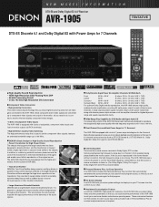
...Channel Surround Back Power Amps for 7.1 Surround The AVR-1905 is too strong. If this low-noise design from the comfort of your TV screen from the higher-end models, like the acclaimed AVR-3805. • Twin Drive Rectifier DENON's Twin Drive Rectifier design uses two rectifying diodes in..., and DTS-ES NEO:6. s On Screen Display The AVR-1905 lets you make system settings via diaplays on all video gear connected to the AVR-1905. s Acclaimed Customization Feature As with all of DENON's high-grade A/V receivers, the AVR-1905 lets you adjust delay times and other parameters so that supports...
...Channel Surround Back Power Amps for 7.1 Surround The AVR-1905 is too strong. If this low-noise design from the comfort of your TV screen from the higher-end models, like the acclaimed AVR-3805. • Twin Drive Rectifier DENON's Twin Drive Rectifier design uses two rectifying diodes in..., and DTS-ES NEO:6. s On Screen Display The AVR-1905 lets you make system settings via diaplays on all video gear connected to the AVR-1905. s Acclaimed Customization Feature As with all of DENON's high-grade A/V receivers, the AVR-1905 lets you adjust delay times and other parameters so that supports...
Literature/Product Sheet
Page 2
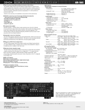
... • Dolby Digital EX • Dolby Pro Logic IIx s 7 Channel Stereo Mode DENON's popular 7 Channel Stereo mode transforms your home theater system, including codes for Multi-Zone Configurations The AVR-1905 provides a Multi Zone Output function and a Select function that let you more accurately match ... -3 dB) (Tone Defeat On) Signal-to drive all six speakers. DENON, LTD. 3-16-11, YUSHIMA, BUNKYO-KU, TOKYO 113-0034, JAPAN 13530704 A s Multi Zone Power Amplifier Assign The AVR-1905's Power Amplifier Assign function lets you assign the Surround Back amplifier channels when ...
... • Dolby Digital EX • Dolby Pro Logic IIx s 7 Channel Stereo Mode DENON's popular 7 Channel Stereo mode transforms your home theater system, including codes for Multi-Zone Configurations The AVR-1905 provides a Multi Zone Output function and a Select function that let you more accurately match ... -3 dB) (Tone Defeat On) Signal-to drive all six speakers. DENON, LTD. 3-16-11, YUSHIMA, BUNKYO-KU, TOKYO 113-0034, JAPAN 13530704 A s Multi Zone Power Amplifier Assign The AVR-1905's Power Amplifier Assign function lets you assign the Surround Back amplifier channels when ...

Owners Manual
Page 2
... intended to alert the user to the presence of uninsulated "dangerous voltage" within an equilateral triangle is encouraged to try to correct the interference by DENON may be determined by turning the product OFF and ON, the user is intended to alert the user to the presence of time. • Dé...
... intended to alert the user to the presence of uninsulated "dangerous voltage" within an equilateral triangle is encouraged to try to correct the interference by DENON may be determined by turning the product OFF and ON, the user is intended to alert the user to the presence of time. • Dé...
Owners Manual
Page 3
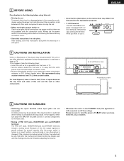
All the safety and operating instructions should be retained for future reference. 3. The safety and operating instructions should be blocked or covered. All warnings on the product. 20. All operating and use instructions should be read before cleaning. Unplug this product, ask the service technician to perform safety checks to determine that the product is provided or the manufacturer's instructions have been adhered to grounding electrodes, and requirements for ventilation and to ensure reliable operation of the product and to dangerous voltage or other products (including ...
All the safety and operating instructions should be retained for future reference. 3. The safety and operating instructions should be blocked or covered. All warnings on the product. 20. All operating and use instructions should be read before cleaning. Unplug this product, ask the service technician to perform safety checks to determine that the product is provided or the manufacturer's instructions have been adhered to grounding electrodes, and requirements for ventilation and to ensure reliable operation of the product and to dangerous voltage or other products (including ...
Owners Manual
Page 4
As this manual before you begin hookup and operation that you for choosing the DENON AVR-1905/785 Digital A / V Surround Receiver. Remote Control Unit 31 ~ 35 ⁄0 Operation 36 ~ 41 ⁄1 Multi Zone 42 ~ 44 ⁄2 Surround 45 ~ 53 ⁄3 DSP Surround ...
As this manual before you begin hookup and operation that you for choosing the DENON AVR-1905/785 Digital A / V Surround Receiver. Remote Control Unit 31 ~ 35 ⁄0 Operation 36 ~ 41 ⁄1 Multi Zone 42 ~ 44 ⁄2 Surround 45 ~ 53 ⁄3 DSP Surround ...
Owners Manual
Page 5
... when you leave home for several seconds after the muting circuit stops functioning. If the volume is used near a tuner or TV. AUX terminal The AVR-1905/785's front panel is still connected on Check once again that there are not problems with a V. If this happens, take the following before using outdoor...
... when you leave home for several seconds after the muting circuit stops functioning. If the volume is used near a tuner or TV. AUX terminal The AVR-1905/785's front panel is still connected on Check once again that there are not problems with a V. If this happens, take the following before using outdoor...
Owners Manual
Page 6
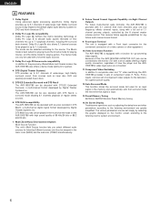
... channels. Dolby Digital Using advanced digital processing algorithms, Dolby Digital provides up to the previously offered Music and Cinema modes, the AVR-1905/785 also offers a Game mode optimum for playing games. Dolby Pro Logic II Game mode compatibility In addition to 5.1 channels of...quality connection, regardless of a video camera or other parameters according to the listening room's system environment. 6 ENGLISH 4 FEATURES 1. The AVR-1905/785 can be also decoded with sources recorded in DTS 96/24, a multi-channel digital signal format developed by selecting the graphic ...
... channels. Dolby Digital Using advanced digital processing algorithms, Dolby Digital provides up to the previously offered Music and Cinema modes, the AVR-1905/785 also offers a Game mode optimum for playing games. Dolby Pro Logic II Game mode compatibility In addition to 5.1 channels of...quality connection, regardless of a video camera or other parameters according to the listening room's system environment. 6 ENGLISH 4 FEATURES 1. The AVR-1905/785 can be also decoded with sources recorded in DTS 96/24, a multi-channel digital signal format developed by selecting the graphic ...

Owners Manual
Page 7
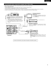
Connecting the audio components • When making connections, also refer to powered loudspeakers. RL Connecting the PRE OUT jacks Use these for connections to "Setting the Digital in Assignment". (See page 26) NOTES: • Use 75 Ω/ohms cable pin cords for coaxial connections. • Use optical cables for optical connections, removing the cap before connecting. Refer to audio equipment with digital input/output jacks Connecting the DIGITAL jacks Use these jacks if you wish to connect external power amplifier(s) to increase the power of the front, center and surround ...
Connecting the audio components • When making connections, also refer to powered loudspeakers. RL Connecting the PRE OUT jacks Use these for connections to "Setting the Digital in Assignment". (See page 26) NOTES: • Use 75 Ω/ohms cable pin cords for coaxial connections. • Use optical cables for optical connections, removing the cap before connecting. Refer to audio equipment with digital input/output jacks Connecting the DIGITAL jacks Use these jacks if you wish to connect external power amplifier(s) to increase the power of the front, center and surround ...

Owners Manual
Page 8
...) to the digital input jacks. Note on connecting the digital input jacks • Only audio signals are two sets of the other components. • The AVR-1905/785 is output to the video signal terminal is equipped with a function for simultaneous recording or video copying. Video input/output connections: • Connect the...
...) to the digital input jacks. Note on connecting the digital input jacks • Only audio signals are two sets of the other components. • The AVR-1905/785 is output to the video signal terminal is equipped with a function for simultaneous recording or video copying. Video input/output connections: • Connect the...
Owners Manual
Page 9
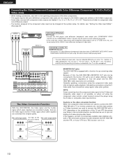
... TV or DBS IN jack using a S-Video connection cord. • VDP can be connected to the VDP jacks in conjunction with each other. • The AVR-1905/785 is equipped with S-Video jacks • When making connections, also refer to the operating instructions of the other components. • A note on page 8. 9 Connect...
... TV or DBS IN jack using a S-Video connection cord. • VDP can be connected to the VDP jacks in conjunction with each other. • The AVR-1905/785 is equipped with S-Video jacks • When making connections, also refer to the operating instructions of the other components. • A note on page 8. 9 Connect...
Owners Manual
Page 10
...This unit's output jacks this unit's internal signals. (Color Diffrence Video jack) (Color Diffrence Video jack) MONITOR OUT jacks The AVR-1905/785 is not possible, so when not using the component video monitor output terminal connect the player using regular video jacks (yellow... difference output. • The function assigned to the VIDEO-2 color difference (component) video jacks. The Video Conversion Function With the AVR-1905/785, the Video signal and the S-video signal which were inputted are converted into a higher quality. ENGLISH Connecting the Video Component Equipped...
...This unit's output jacks this unit's internal signals. (Color Diffrence Video jack) (Color Diffrence Video jack) MONITOR OUT jacks The AVR-1905/785 is not possible, so when not using the component video monitor output terminal connect the player using regular video jacks (yellow... difference output. • The function assigned to the VIDEO-2 color difference (component) video jacks. The Video Conversion Function With the AVR-1905/785, the Video signal and the S-video signal which were inputted are converted into a higher quality. ENGLISH Connecting the Video Component Equipped...

Owners Manual
Page 11
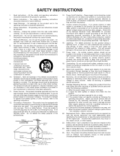
GROUND An F-type FM antenna cable plug can be connected to the grounding system of the building, as close to the point of AM antennas 1. Insert the conductor. 3. Bend in particular, specifies that the cable ground shall be connected directly. Return the lever. Connecting the antenna terminals FM INDOOR ANTENNA (An Accessory) DIRECTION OF BROADCASTING STATION FM ANTENNA 75 Ω/ohms COAXIAL CABLE ENGLISH AM OUTDOOR ANTENNA AM LOOP ANTENNA (An Accessory) AM loop antenna assembly Connect to a wall. With the antenna on wall, etc. Mount b. Installation hole Mount on...
GROUND An F-type FM antenna cable plug can be connected to the grounding system of the building, as close to the point of AM antennas 1. Insert the conductor. 3. Bend in particular, specifies that the cable ground shall be connected directly. Return the lever. Connecting the antenna terminals FM INDOOR ANTENNA (An Accessory) DIRECTION OF BROADCASTING STATION FM ANTENNA 75 Ω/ohms COAXIAL CABLE ENGLISH AM OUTDOOR ANTENNA AM LOOP ANTENNA (An Accessory) AM loop antenna assembly Connect to a wall. With the antenna on wall, etc. Mount b. Installation hole Mount on...
Owners Manual
Page 12
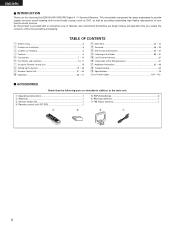
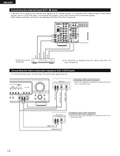
IN) jacks, see page 39. LR LINE OUT DIGITAL OUT VIDEO OUT Video camera OUTPUT R L VIDEO OUT RL LINE OUT VIDEO OUT Connecting a video camera component • Connect the video camera component's output jacks to this unit's V. AUX INPUT jacks. ENGLISH Connecting the external input (EXT. R L R L Front Surround Subwoofer Center Decoder with 6-channel analog output For instructions on playback using a 75 Ω/ohms video signal cable cord. IN) jacks • These jacks are for inputting multi-channel audio signals from an outboard decoder, or a component with V.AUX jacks &#...
IN) jacks, see page 39. LR LINE OUT DIGITAL OUT VIDEO OUT Video camera OUTPUT R L VIDEO OUT RL LINE OUT VIDEO OUT Connecting a video camera component • Connect the video camera component's output jacks to this unit's V. AUX INPUT jacks. ENGLISH Connecting the external input (EXT. R L R L Front Surround Subwoofer Center Decoder with 6-channel analog output For instructions on playback using a 75 Ω/ohms video signal cable cord. IN) jacks • These jacks are for inputting multi-channel audio signals from an outboard decoder, or a component with V.AUX jacks &#...
Owners Manual
Page 13
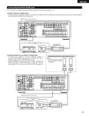
In this speaker for ZONE2. RL ZONE2 Integrated pre-main amplifier B RC-617 INFRARED SENSOR OUTPUT + RC-616 INFRARED RETRANSMITTER INPUT + AUX OUT [2] ZONE2 SPEAKER OUT and PREOUT CONNECTIONS • If another pre-main (integrated) amplifier is connected, the ZONE2 Fixed-out (variable/fixed level) jacks can be used for MAIN ZONE. (See page 29) SURROUND BACK/MULTI ZONE SPEAKER SYSTEMS NOTE: • The settings must be changed to use this case , Surround Back Speaker OUT cannot be used when "ZONE2" is connected, the ZONE2 output terminals can be used to play a different program...
In this speaker for ZONE2. RL ZONE2 Integrated pre-main amplifier B RC-617 INFRARED SENSOR OUTPUT + RC-616 INFRARED RETRANSMITTER INPUT + AUX OUT [2] ZONE2 SPEAKER OUT and PREOUT CONNECTIONS • If another pre-main (integrated) amplifier is connected, the ZONE2 Fixed-out (variable/fixed level) jacks can be used for MAIN ZONE. (See page 29) SURROUND BACK/MULTI ZONE SPEAKER SYSTEMS NOTE: • The settings must be changed to use this case , Surround Back Speaker OUT cannot be used when "ZONE2" is connected, the ZONE2 output terminals can be used to play a different program...
Owners Manual
Page 14
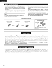
... extreme temperature rise. Note on . Turn off and the power supply indicator LED flashes. If the protection circuit is cut off the power and contact a DENON service center. Mismatching of polarities will result in electric shocks. Improve the ventilation condition around the set is very hot. The purpose of this unit...
... extreme temperature rise. Note on . Turn off and the power supply indicator LED flashes. If the protection circuit is cut off the power and contact a DENON service center. Mismatching of polarities will result in electric shocks. Improve the ventilation condition around the set is very hot. The purpose of this unit...
Owners Manual
Page 15
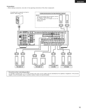
If this should happen, move the speaker away to use Surround back with built-in amplifier (super woofer), etc. BACK L CH. • The settings must be disturbed by the speaker's magnetism. SURROUND BACK/MULTI ZONE SPEAKER SYSTEMS NOTES: • To use this effect. 15 See page 29. (L) (R) ENGLISH (L) (R) FRONT SPEAKER SYSTEMS (B) (L) (R) FRONT SPEAKER SYSTEMS (A) CENTER SPEAKER SYSTEM (L) (R) SURROUND SPEAKER SYSTEMS • Precautions when connecting speakers If a speaker is placed near a TV or video monitor, the colors on the screen may be changed to a position ...
If this should happen, move the speaker away to use Surround back with built-in amplifier (super woofer), etc. BACK L CH. • The settings must be disturbed by the speaker's magnetism. SURROUND BACK/MULTI ZONE SPEAKER SYSTEMS NOTES: • To use this effect. 15 See page 29. (L) (R) ENGLISH (L) (R) FRONT SPEAKER SYSTEMS (B) (L) (R) FRONT SPEAKER SYSTEMS (A) CENTER SPEAKER SYSTEM (L) (R) SURROUND SPEAKER SYSTEMS • Precautions when connecting speakers If a speaker is placed near a TV or video monitor, the colors on the screen may be changed to a position ...
Owners Manual
Page 16
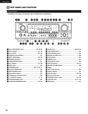
IN button 37, 39) o BAND button 59) !0 STANDARD button 45, 47, 49, 51) !1 5CH/7CH STEREO button 55) !2 DIRECT/STEREO button 39) !3 Preset station buttons 60) !4 TUNING • (up) / ª (down) buttons 59) !5 V. AUX INPUT terminals 5, 12) !6 SURROUND MODE button 38) !7 SURROUND PARAMETER button 47, 55) !8 SELECT knob 38, 48, 56) !9 TONE DEFEAT button 40) @0 TONE CONTROL button 40) @1 MASTER VOLUME control 38) @2 STATUS button 41) @3 DIMMER button 41) @4 VIDEO SELECT button 40) @5 OUTPUT indicators 44, 51) @6 MASTER VOLUME indicator 38) @7 Display @8 INPUT mode ...
IN button 37, 39) o BAND button 59) !0 STANDARD button 45, 47, 49, 51) !1 5CH/7CH STEREO button 55) !2 DIRECT/STEREO button 39) !3 Preset station buttons 60) !4 TUNING • (up) / ª (down) buttons 59) !5 V. AUX INPUT terminals 5, 12) !6 SURROUND MODE button 38) !7 SURROUND PARAMETER button 47, 55) !8 SELECT knob 38, 48, 56) !9 TONE DEFEAT button 40) @0 TONE CONTROL button 40) @1 MASTER VOLUME control 38) @2 STATUS button 41) @3 DIMMER button 41) @4 VIDEO SELECT button 40) @5 OUTPUT indicators 44, 51) @6 MASTER VOLUME indicator 38) @7 Display @8 INPUT mode ...
Owners Manual
Page 17
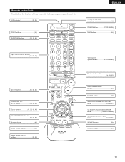
LED (indicator 32, 35) ZONE2 buttons 44) SURROUND buttons 38, 45, 55) ENGLISH Remote control signal transmitter 18) POWER buttons 21, 32~34, 36) MAIN buttons 44) Input source selector buttons 32~35, 37) System buttons 31, 33, 34) SYSTEM SET UP/ SETUP button 19, 33, 34) Cursor buttons 19, 33, 34, 48) ON SCREEN/DISPLAY button 33, 34, 53) Test tone button 45) VIDEO SELECT button 40) INPUT MODE selector buttons 37, 39) Tuner system/ System buttons 31, 33, 34, 59) Mode selector switches 31~33, 35) Master volume control buttons 38) MUTING button 40) SURROUND PARAMETER/SYSTEM ...
LED (indicator 32, 35) ZONE2 buttons 44) SURROUND buttons 38, 45, 55) ENGLISH Remote control signal transmitter 18) POWER buttons 21, 32~34, 36) MAIN buttons 44) Input source selector buttons 32~35, 37) System buttons 31, 33, 34) SYSTEM SET UP/ SETUP button 19, 33, 34) Cursor buttons 19, 33, 34, 48) ON SCREEN/DISPLAY button 33, 34, 53) Test tone button 45) VIDEO SELECT button 40) INPUT MODE selector buttons 37, 39) Tuner system/ System buttons 31, 33, 34, 59) Mode selector switches 31~33, 35) Master volume control buttons 38) MUTING button 40) SURROUND PARAMETER/SYSTEM ...
Owners Manual
Page 18
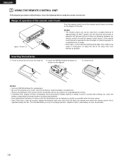
Clean the battery compartment thoroughly before using the remote control unit. Replace it come in malfunction, so keep the set . (The included battery is exposed to direct sunlight or other strong light, or if operated from a straight distance of approximately 23 feet/7 meters, but this distance will shorten or operation will become difficult if there are correct. (See the illustration inside the battery compartment.) • Remove the batteries if the remote control transmitter will not be used for verifying operation. Range of operation of them immediately. Avoid ...
Clean the battery compartment thoroughly before using the remote control unit. Replace it come in malfunction, so keep the set . (The included battery is exposed to direct sunlight or other strong light, or if operated from a straight distance of approximately 23 feet/7 meters, but this distance will shorten or operation will become difficult if there are correct. (See the illustration inside the battery compartment.) • Remove the batteries if the remote control transmitter will not be used for verifying operation. Range of operation of them immediately. Avoid ...
Owners Manual
Page 19
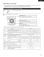
... to "AUDIO". 2 Use the following buttons to set up the listening room's AV system centered around the AVR-1905/785. Also use for Zone 2. Set the frequency (Hz) below on the monitor screen using the AVR-1905/785's on the display. Large Front L Front R 12 ft 12 ft Front L Front R 0 dB 0 dB Center Sp...
... to "AUDIO". 2 Use the following buttons to set up the listening room's AV system centered around the AVR-1905/785. Also use for Zone 2. Set the frequency (Hz) below on the monitor screen using the AVR-1905/785's on the display. Large Front L Front R 12 ft 12 ft Front L Front R 0 dB 0 dB Center Sp...
