

Owners Manual
Page 8
... 21, 31~33, 35) MAIN ZONE buttons 34, 42) Input source selector buttons 31~34, 36, 45) System buttons 30, 32, 33) SYSTEM SET UP/ SETUP button 20, 29, 32) Cursor buttons 20, 32, 44, 51) ON SCREEN/DISPLAY button 32, 40) Test tone button 43) VIDEO SELECT button 39) INPUT...
... 21, 31~33, 35) MAIN ZONE buttons 34, 42) Input source selector buttons 31~34, 36, 45) System buttons 30, 32, 33) SYSTEM SET UP/ SETUP button 20, 29, 32) Cursor buttons 20, 32, 44, 51) ON SCREEN/DISPLAY button 32, 40) Test tone button 43) VIDEO SELECT button 39) INPUT...
Owners Manual
Page 9
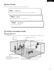
... the TV or screen with their front surfaces as flush with the front of the screen as possible. Surround speaker systems 9 Step 3 (page 20 to setup the Speakers and connecting the components. ENGLISH 7 SETTING UP THE SPEAKER SYSTEMS 2 Speaker system layout Basic system layout • The following is an example of..., setting up the system. Step 2 (page 19) Next, insert the batteries into the remote control unit. 6 READ THIS FIRST This AV Surround Receiver must be setup before use.
... the TV or screen with their front surfaces as flush with the front of the screen as possible. Surround speaker systems 9 Step 3 (page 20 to setup the Speakers and connecting the components. ENGLISH 7 SETTING UP THE SPEAKER SYSTEMS 2 Speaker system layout Basic system layout • The following is an example of..., setting up the system. Step 2 (page 19) Next, insert the batteries into the remote control unit. 6 READ THIS FIRST This AV Surround Receiver must be setup before use.
Owners Manual
Page 13
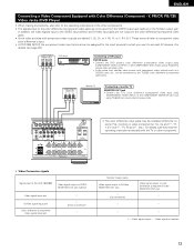
...; When making connections, also refer to the operating instructions of the other component. • Video Conversion signals Signal input to the AVR-1804/884 Video signal output to VIDEO MONITOR OUT jack (yellow) Video signal input jack S-Video signal input jack Color difference (component) Video... (C : Video signal output, E : Video signal not output) 13 These terms all refer to component video color difference output. • At SYSTEM SETUP, the component video input terminal can be connected to the COMPONENT DVD IN jack using 75 Ω/ohms coaxial video pin-plug cords. • In...
...; When making connections, also refer to the operating instructions of the other component. • Video Conversion signals Signal input to the AVR-1804/884 Video signal output to VIDEO MONITOR OUT jack (yellow) Video signal input jack S-Video signal input jack Color difference (component) Video... (C : Video signal output, E : Video signal not output) 13 These terms all refer to component video color difference output. • At SYSTEM SETUP, the component video input terminal can be connected to the COMPONENT DVD IN jack using 75 Ω/ohms coaxial video pin-plug cords. • In...
Owners Manual
Page 20
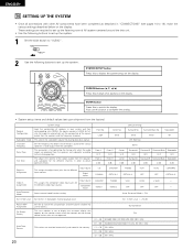
... set the composition of the signals output from the factory) Speaker Configuration Subwoofer mode Crossover Frequency Delay Time Test Tone System setup Input the combination of speakers in your system and their corresponding sizes (SMALL for regular speakers, LARGE for fullsize, full-range...) to complete the setting. • System setup items and default values (set upon shipment from the speakers and the frequency response. Also use for Assignment the different video input ...
... set the composition of the signals output from the factory) Speaker Configuration Subwoofer mode Crossover Frequency Delay Time Test Tone System setup Input the combination of speakers in your system and their corresponding sizes (SMALL for regular speakers, LARGE for fullsize, full-range...) to complete the setting. • System setup items and default values (set upon shipment from the speakers and the frequency response. Also use for Assignment the different video input ...
Owners Manual
Page 21
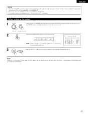
The changes to the settings made up . ENGLISH NOTES: • The AVR-1804/884's on-screen display function is selected. NOTE: Press the SYSTEM SETUP button again to finish system set up to that all the components are correct, then press the POWER operation switch on the main unit or ...the POWER button on the remote control unit to turn on the power. (Main unit) (Remote control unit) 2 Press the SYSTEM SETUP button to the speaker configuration set up can be difficult to read small characters on the remote control unit. 3 Press the ENTER or (down) button...
The changes to the settings made up . ENGLISH NOTES: • The AVR-1804/884's on-screen display function is selected. NOTE: Press the SYSTEM SETUP button again to finish system set up to that all the components are correct, then press the POWER operation switch on the main unit or ...the POWER button on the remote control unit to turn on the power. (Main unit) (Remote control unit) 2 Press the SYSTEM SETUP button to the speaker configuration set up can be difficult to read small characters on the remote control unit. 3 Press the ENTER or (down) button...

Owners Manual
Page 22
..." when it's not installed. Surround Sp. Select this setting is divided to subwoofer channel and not reproduced in function of your speaker systems. Performing this setup optimizes the system. • The composition of the signals output to the different channels and the frequency response are connected and, if so, their size...
..." when it's not installed. Surround Sp. Select this setting is divided to subwoofer channel and not reproduced in function of your speaker systems. Performing this setup optimizes the system. • The composition of the signals output to the different channels and the frequency response are connected and, if so, their size...

Owners Manual
Page 23
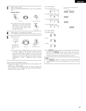
Assignment of channels set to "SMALL" in the setup. NOTE: For ordinary speaker systems, we recommend setting the crossover frequency to the SPEAKER DISTANCE NOTES: - Therefore, the low frequency signal range that are played ... signal range of channels set to "Large" are LFE signals (during Dolby Digital or DTS signal playback) and the channel specified as "Small" in the setup menu. • Select the play the low frequency signal range of the channel selected with a frequency below which the bass sound of the subwoofer mode...
Assignment of channels set to "SMALL" in the setup. NOTE: For ordinary speaker systems, we recommend setting the crossover frequency to the SPEAKER DISTANCE NOTES: - Therefore, the low frequency signal range that are played ... signal range of channels set to "Large" are LFE signals (during Dolby Digital or DTS signal playback) and the channel specified as "Small" in the setup menu. • Select the play the low frequency signal range of the channel selected with a frequency below which the bass sound of the subwoofer mode...
Owners Manual
Page 29
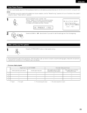
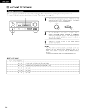
"Search" flashes on the screen and searching begins. ENGLISH Auto Tuner Presets Use this to automatically search for FM broadcasts and store up to 40 stations at preset channels A1 to 8, B1 to 8, C1 to 8, D1 to 8 and E1 to screen. 26 PRESET The display automatically switches to 8. NOTE: • If an FM station cannot be preset automatically due to poor reception, use the "Manual tuning" operation to tune in the station, then preset it using the manual "Preset memory" operation. 1 Use the CURSOR button to select "Yes". "Completed" appears once searching is completed.
"Search" flashes on the screen and searching begins. ENGLISH Auto Tuner Presets Use this to automatically search for FM broadcasts and store up to 40 stations at preset channels A1 to 8, B1 to 8, C1 to 8, D1 to 8 and E1 to screen. 26 PRESET The display automatically switches to 8. NOTE: • If an FM station cannot be preset automatically due to poor reception, use the "Manual tuning" operation to tune in the station, then preset it using the manual "Preset memory" operation. 1 Use the CURSOR button to select "Yes". "Completed" appears once searching is completed.
Owners Manual
Page 32
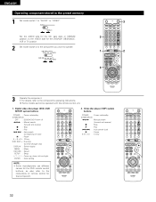
... side for the CD, tape deck or CDR/MD position, to the component's operating instructions. Digital video disc player (DVD, DVD SETUP) system buttons POWER : Power on/standby (ON/SOURCE) OFF : DENON DVD Power off 6,7 : Manual search (forward and reverse) 2 : Stop 1 : Play 8,9 : Auto search (to beginning of track) 3 : Pause 0 ~ 9, +10 : 10 key...
... side for the CD, tape deck or CDR/MD position, to the component's operating instructions. Digital video disc player (DVD, DVD SETUP) system buttons POWER : Power on/standby (ON/SOURCE) OFF : DENON DVD Power off 6,7 : Manual search (forward and reverse) 2 : Stop 1 : Play 8,9 : Auto search (to beginning of track) 3 : Pause 0 ~ 9, +10 : 10 key...
Owners Manual
Page 37
... playback on . Press the SURROUND MODE button, then turn the SELECT knob. If the DIGITAL indicator does not light, check whether the digital input component setup (page 26) and connections are being input properly. When playing DTS-compatible sources, be heard. 37 Input mode display • In the AUTO mode AUTO...
... playback on . Press the SURROUND MODE button, then turn the SELECT knob. If the DIGITAL indicator does not light, check whether the digital input component setup (page 26) and connections are being input properly. When playing DTS-compatible sources, be heard. 37 Input mode display • In the AUTO mode AUTO...
Owners Manual
Page 41
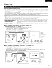
... be controlled from zone2 using LINE OUT) "POWER AMP ASSIGNMENT" setting is selected at System Setup Menu "Power Amp Assignment". ENGLISH 13 MULTI ZONE Multi-zone playback with ZONE2 mode : SPEAKER cable RC-617 AVR-1804/884 FL C FR SW SL RC-616 REMOTE CONTROL UNIT SR (Light) (Main unit's...'s ZONE2 VOLUME + and - POWER AMP ASSIGNMENT setting.....Set this unit and the playback devices are installed. (Refer to -room remote control unit (DENON RC-616, 617 or 618) is wired and connected between the main zone and zone2, the remote-controllable devices in which this to switch the...
... be controlled from zone2 using LINE OUT) "POWER AMP ASSIGNMENT" setting is selected at System Setup Menu "Power Amp Assignment". ENGLISH 13 MULTI ZONE Multi-zone playback with ZONE2 mode : SPEAKER cable RC-617 AVR-1804/884 FL C FR SW SL RC-616 REMOTE CONTROL UNIT SR (Light) (Main unit's...'s ZONE2 VOLUME + and - POWER AMP ASSIGNMENT setting.....Set this unit and the playback devices are installed. (Refer to -room remote control unit (DENON RC-616, 617 or 618) is wired and connected between the main zone and zone2, the remote-controllable devices in which this to switch the...

Owners Manual
Page 43
... using the test tones is the same for the different modes are output from the different speakers. This adjustment can be performed with the system setup (see page 20) or from the remote control unit, as described below. • Adjusting with the surround function, be sure to use the test tones...
... using the test tones is the same for the different modes are output from the different speakers. This adjustment can be performed with the system setup (see page 20) or from the remote control unit, as described below. • Adjusting with the surround function, be sure to use the test tones...

Owners Manual
Page 49
... the ENTER button to OFF for overly-bright sounding motion picture soundtracks. These contents can be verified with the subwoofer peak limit level setting (system setup menu), adjust the level as DVD, DTV and other future formats that the LFE LEVEL be set to the standard level. Set to finish surround...
... the ENTER button to OFF for overly-bright sounding motion picture soundtracks. These contents can be verified with the subwoofer peak limit level setting (system setup menu), adjust the level as DVD, DTV and other future formats that the LFE LEVEL be set to the standard level. Set to finish surround...
Owners Manual
Page 54
..." operation to E8, for FM broadcast stations. 1 2 When the first FM broadcast station is found, that station is stored in the preset memory at "System setup". (See page 29.) 1 1 When the main unit's power operation switch turn on while pressing the set's PRESET D button the unit automatically begins searching for a maximum...
..." operation to E8, for FM broadcast stations. 1 2 When the first FM broadcast station is found, that station is stored in the preset memory at "System setup". (See page 29.) 1 1 When the main unit's power operation switch turn on while pressing the set's PRESET D button the unit automatically begins searching for a maximum...


