
Owners Manual
Page 4
...instructions along with a V. Remove the cap covering the terminal when you for explanation purposes. • V. AUX terminal The AVR-1705/685's front panel is provided with an immense array of your favorite music sources. TABLE OF CONTENTS z Before Using 4 x... of features, we recommend that the illustrations in a safe place. Always set the power operation switch to the standby position before connecting and disconnecting connection cords. • Store this first 9 m Setting up the System 18 ~...when moving the set for choosing the DENON A/V Surround receiver.
...instructions along with a V. Remove the cap covering the terminal when you for explanation purposes. • V. AUX terminal The AVR-1705/685's front panel is provided with an immense array of your favorite music sources. TABLE OF CONTENTS z Before Using 4 x... of features, we recommend that the illustrations in a safe place. Always set the power operation switch to the standby position before connecting and disconnecting connection cords. • Store this first 9 m Setting up the System 18 ~...when moving the set for choosing the DENON A/V Surround receiver.
Owners Manual
Page 5
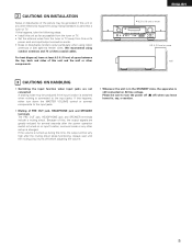
... noise may be generated if this happens, either turn the power off (£ off before adjusting the volume. • Whenever the unit is in the STANDBY state, the apparatus is still connected on or input function, surround mode or any other electronic equipment using microprocessors is used near a tuner or TV...
... noise may be generated if this happens, either turn the power off (£ off before adjusting the volume. • Whenever the unit is in the STANDBY state, the apparatus is still connected on or input function, surround mode or any other electronic equipment using microprocessors is used near a tuner or TV...
Owners Manual
Page 7
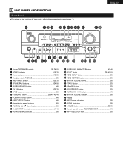
... NAMES AND FUNCTIONS Front Panel • For details on the functions of these parts, refer to the pages given in parentheses ( ). #2 #1 #0 @9 @8 @7 @6 @5@4 @3 @2 ENGLISH @1 @0 r u o !1 !3 q w e ty i !0 !2 !4 !5 !6 !7 !8 !9 q Power ON/STANDBY switch 19, 34, 53) w POWER indicator 19, 34) e Power switch 19, 34) r Headphone jack (PHONES 37) t INPUT MODE button 35, 38) y SPEAKER A/B buttons 34, 56...
... NAMES AND FUNCTIONS Front Panel • For details on the functions of these parts, refer to the pages given in parentheses ( ). #2 #1 #0 @9 @8 @7 @6 @5@4 @3 @2 ENGLISH @1 @0 r u o !1 !3 q w e ty i !0 !2 !4 !5 !6 !7 !8 !9 q Power ON/STANDBY switch 19, 34, 53) w POWER indicator 19, 34) e Power switch 19, 34) r Headphone jack (PHONES 37) t INPUT MODE button 35, 38) y SPEAKER A/B buttons 34, 56...
Owners Manual
Page 10
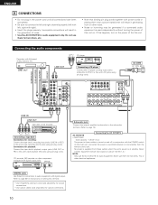
... tape deck Connections for recording: Connect the tape deck's recording input jacks (LINE IN or REC) to page 26 for instructions on and standby from these for audio equipment. Connecting the audio components Decoders with right). • Insert the plugs securely. Connections for playback: Connect the tape...plug in the generation of noise. • Use the AC OUTLETS for audio equipment only. Never connect equipment whose total capacity is at standby. DIGITAL jacks Use these outlets when this unit. Do not use them for hair driers, etc. • Note that binding pin plug ...
... tape deck Connections for recording: Connect the tape deck's recording input jacks (LINE IN or REC) to page 26 for instructions on and standby from these for audio equipment. Connecting the audio components Decoders with right). • Insert the plugs securely. Connections for playback: Connect the tape...plug in the generation of noise. • Use the AC OUTLETS for audio equipment only. Never connect equipment whose total capacity is at standby. DIGITAL jacks Use these outlets when this unit. Do not use them for hair driers, etc. • Note that binding pin plug ...

Owners Manual
Page 19
... make sure the "AUDIO" position of the slide switch on and off . System set up can be finished at any time. Press the Power ON/STANDBY switch (button). (Main unit) (Remote control unit) 4 Press the SYSTEM SETUP button to the surround speaker setting. NOTE: • When "Small" has been selected for...
... make sure the "AUDIO" position of the slide switch on and off . System set up can be finished at any time. Press the Power ON/STANDBY switch (button). (Main unit) (Remote control unit) 4 Press the SYSTEM SETUP button to the surround speaker setting. NOTE: • When "Small" has been selected for...
Owners Manual
Page 31
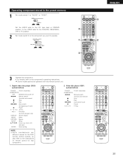
... ENGLISH 3 2 3 Operate the component. • For details, refer to "AUDIO" or "VIDEO". Digital video disc player (DVD) system buttons POWER : Power on/standby (ON/SOURCE) OFF : DENON DVD power off 6,7 : Manual search (forward and reverse) 2 : Stop 1 : Play 8,9 : Auto search (to beginning of track) 3 : Pause 0 ~... ENTER : Enter setting NOTE: • Some manufacturers use different names for the DVD remote control buttons, so also refer to the instructions on /standby (ON/SOURCE) 6,7 : Manual search (forward and reverse) 2 : Stop 1 : Play 8,9 : Auto search (cue) 3 : Pause 0~9,...
... ENGLISH 3 2 3 Operate the component. • For details, refer to "AUDIO" or "VIDEO". Digital video disc player (DVD) system buttons POWER : Power on/standby (ON/SOURCE) OFF : DENON DVD power off 6,7 : Manual search (forward and reverse) 2 : Stop 1 : Play 8,9 : Auto search (to beginning of track) 3 : Pause 0 ~... ENTER : Enter setting NOTE: • Some manufacturers use different names for the DVD remote control buttons, so also refer to the instructions on /standby (ON/SOURCE) 6,7 : Manual search (forward and reverse) 2 : Stop 1 : Play 8,9 : Auto search (cue) 3 : Pause 0~9,...
Owners Manual
Page 32
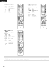
...- 0~9, +10 : Channels DISPLAY : Switch display VOL +, - : Volume up /down 5. Digital broadcast satellite (DBS) tuner and cable (CABLE) system buttons POWER : Power on /standby (ON/SOURCE) 6,7 : Manual search (forward and reverse) 2 : Stop 1 : Play 3 : Pause Channel +, - : Channels 4. Video deck (VCR) system buttons POWER : Power on.../down +, - NOTES: • For this CD, CDR, MD and TAPE components, buttons can be operated in the same way as for DENON audio components (page 29). • The TV can be operated when the switch is at DVD/VDP, VCR, TV position. 32 ENGLISH 3.
...- 0~9, +10 : Channels DISPLAY : Switch display VOL +, - : Volume up /down 5. Digital broadcast satellite (DBS) tuner and cable (CABLE) system buttons POWER : Power on /standby (ON/SOURCE) 6,7 : Manual search (forward and reverse) 2 : Stop 1 : Play 3 : Pause Channel +, - : Channels 4. Video deck (VCR) system buttons POWER : Power on.../down +, - NOTES: • For this CD, CDR, MD and TAPE components, buttons can be operated in the same way as for DENON audio components (page 29). • The TV can be operated when the switch is at DVD/VDP, VCR, TV position. 32 ENGLISH 3.
Owners Manual
Page 34
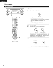
Press the Power ON/STANDBY switch (button). (Main unit) (Remote control unit) When pressed, the power turns on and the display lights. The sound is set and the display turns ... this position, the power cannot be changed with the SPEAKER button on the remote control unit. 34 When pressed again, the power turns off, the standby mode is muted for several seconds, after which the unit operates normally. ENGLISH 12 OPERATION Before operating 21 3 2 3 Preparations: Check that all connections are proper...
Press the Power ON/STANDBY switch (button). (Main unit) (Remote control unit) When pressed, the power turns on and the display lights. The sound is set and the display turns ... this position, the power cannot be changed with the SPEAKER button on the remote control unit. 34 When pressed again, the power turns off, the standby mode is muted for several seconds, after which the unit operates normally. ENGLISH 12 OPERATION Before operating 21 3 2 3 Preparations: Check that all connections are proper...

Owners Manual
Page 64
...; Press the proper button. - • < and > ends of the front channel being input. 15, 16 35 36 37 36 DISPLAY not displayed and the "ON/STANDBY" LED flashes at continuous high power conditions and/or inadequate ventilation. • Switch power off, connect speakers properly, then switch power back on . • Turn...
...; Press the proper button. - • < and > ends of the front channel being input. 15, 16 35 36 37 36 DISPLAY not displayed and the "ON/STANDBY" LED flashes at continuous high power conditions and/or inadequate ventilation. • Switch power off, connect speakers properly, then switch power back on . • Turn...


