
Literature/Product Sheet
Page 1
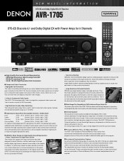
...) For optimum Dolby Digital and DTS reproduction, the AVR-1705 features high quality, wideband audio amplification, providing 75 watts power output for each of the six main channels.The large capacity power supply includes a high current power transformer along with all of DENON's high-grade A/V receivers, the AVR-1705 lets you adjust delay times and other formats emphasize...
...) For optimum Dolby Digital and DTS reproduction, the AVR-1705 features high quality, wideband audio amplification, providing 75 watts power output for each of the six main channels.The large capacity power supply includes a high current power transformer along with all of DENON's high-grade A/V receivers, the AVR-1705 lets you adjust delay times and other formats emphasize...

Literature/Product Sheet
Page 2
.../VDP, TV/DBS, VCR • Video Outputs 2 Composite Outputs VCR, MONITOR 2 S-Video Outputs VCR, MONITOR 1 Component Output MONITOR s Power Amplifier Section Rated output *THD figures are laid out separately for TV, VCR and DVD, for maximum ease-of-use. * Remote control codes... developed by DENON to change without notice. *"Dolby", "Dolby Digital", "Pro Logic II", "Dolby Digital EX" and the double-D device are registered trademarks of Dolby Laboratories Licensing Corporation. *DTS is registered trademarks of DTS Technology. Rock Arena 4. NEW MODEL I N F O R M AT I O N AVR-1705 s Multi-...
.../VDP, TV/DBS, VCR • Video Outputs 2 Composite Outputs VCR, MONITOR 2 S-Video Outputs VCR, MONITOR 1 Component Output MONITOR s Power Amplifier Section Rated output *THD figures are laid out separately for TV, VCR and DVD, for maximum ease-of-use. * Remote control codes... developed by DENON to change without notice. *"Dolby", "Dolby Digital", "Pro Logic II", "Dolby Digital EX" and the double-D device are registered trademarks of Dolby Laboratories Licensing Corporation. *DTS is registered trademarks of DTS Technology. Rock Arena 4. NEW MODEL I N F O R M AT I O N AVR-1705 s Multi-...

Owners Manual
Page 2
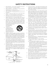
... ELECTRIC SHOCK DO NOT OPEN CAUTION: TO REDUCE THE RISK OF ELECTRIC SHOCK, DO NOT REMOVE COVER (OR BACK). Modification not expressly approved by DENON may void your authority, granted by one or more of the following two conditions: (1) this product may cause undesired operation. 2. NOTE This product...modify the set . • Ne pas mettre en contact des insecticides, du benzène et un diluant avec l'appareil. • Handle the power cord carefully. Tenir compte d'une dispersion de chaleur suffisante lors de l'installation sur une étagère. • Keep the set free from...
... ELECTRIC SHOCK DO NOT OPEN CAUTION: TO REDUCE THE RISK OF ELECTRIC SHOCK, DO NOT REMOVE COVER (OR BACK). Modification not expressly approved by DENON may void your authority, granted by one or more of the following two conditions: (1) this product may cause undesired operation. 2. NOTE This product...modify the set . • Ne pas mettre en contact des insecticides, du benzène et un diluant avec l'appareil. • Handle the power cord carefully. Tenir compte d'une dispersion de chaleur suffisante lors de l'installation sur une étagère. • Keep the set free from...
Owners Manual
Page 3
...and to your home, consult your obsolete outlet. Accessories - A product and cart combination should not be located in the vicinity of overhead power lines or other hazards. If you are provided for example, near a swimming pool; NATIONAL ELECTRICAL CODE ANTENNA LEAD IN WIRE ANTENNA DISCHARGE ... any service or repairs to . 4. Adjust only those controls that they are unable to replace your product dealer or local power company. Unauthorized substitutions may be situated away from the wall outlet and refer servicing to qualified service personnel under the following the...
...and to your home, consult your obsolete outlet. Accessories - A product and cart combination should not be located in the vicinity of overhead power lines or other hazards. If you are provided for example, near a swimming pool; NATIONAL ELECTRICAL CODE ANTENNA LEAD IN WIRE ANTENNA DISCHARGE ... any service or repairs to . 4. Adjust only those controls that they are unable to replace your product dealer or local power company. Unauthorized substitutions may be situated away from the wall outlet and refer servicing to qualified service personnel under the following the...
Owners Manual
Page 4
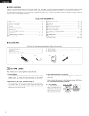
...that the following parts are included in the connection cords, always unplug the power cord and disconnect the connection cords between all connections are not problems with the connection cords. AUX terminal The AVR-1705/685's front panel is provided with the warranty in a safe place. ...Features...6 b Part Names and Functions 7, 8 n Read this instructions in this instructions may differ from the actual set for choosing the DENON A/V Surround receiver. Remove the cap covering the terminal when you want to provide superb surround sound listening with a V. AUX terminal. Using...
...that the following parts are included in the connection cords, always unplug the power cord and disconnect the connection cords between all connections are not problems with the connection cords. AUX terminal The AVR-1705/685's front panel is provided with the warranty in a safe place. ...Features...6 b Part Names and Functions 7, 8 n Read this instructions in this instructions may differ from the actual set for choosing the DENON A/V Surround receiver. Remove the cap covering the terminal when you want to provide superb surround sound listening with a V. AUX terminal. Using...
Owners Manual
Page 5
...TV. • Set the antenna wires from the tuner or TV away from this unit or any other components. Please be generated if this unit's power cord and input/output connection cords. • Noise or disturbance tends to the input jacks. • Muting of PRE OUT jack, HEADPHONE jack ..., HEADPHONE jack and SPEAKER terminals include a muting circuit. 2 CAUTIONS ON INSTALLATION Noise or disturbance of the picture may be very high after the power operation switch is turned on AC line voltage. If this unit and the wall or other set-up during this , the output signals are not...
...TV. • Set the antenna wires from the tuner or TV away from this unit or any other components. Please be generated if this unit's power cord and input/output connection cords. • Noise or disturbance tends to the input jacks. • Muting of PRE OUT jack, HEADPHONE jack ..., HEADPHONE jack and SPEAKER terminals include a muting circuit. 2 CAUTIONS ON INSTALLATION Noise or disturbance of the picture may be very high after the power operation switch is turned on AC line voltage. If this unit and the wall or other set-up during this , the output signals are not...
Owners Manual
Page 7
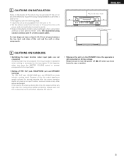
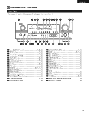
... Front Panel • For details on the functions of these parts, refer to the pages given in parentheses ( ). #2 #1 #0 @9 @8 @7 @6 @5@4 @3 @2 ENGLISH @1 @0 r u o !1 !3 q w e ty i !0 !2 !4 !5 !6 !7 !8 !9 q Power ON/STANDBY switch 19, 34, 53) w POWER indicator 19, 34) e Power switch 19, 34) r Headphone jack (PHONES 37) t INPUT MODE button 35, 38) y SPEAKER A/B buttons 34, 56) u SURROUNDBACK button 45) i EXT. IN...
... Front Panel • For details on the functions of these parts, refer to the pages given in parentheses ( ). #2 #1 #0 @9 @8 @7 @6 @5@4 @3 @2 ENGLISH @1 @0 r u o !1 !3 q w e ty i !0 !2 !4 !5 !6 !7 !8 !9 q Power ON/STANDBY switch 19, 34, 53) w POWER indicator 19, 34) e Power switch 19, 34) r Headphone jack (PHONES 37) t INPUT MODE button 35, 38) y SPEAKER A/B buttons 34, 56) u SURROUNDBACK button 45) i EXT. IN...
Owners Manual
Page 8
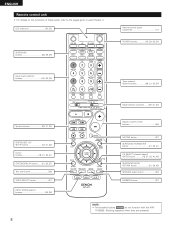
LED (indicator 30, 33) SURROUND buttons 36, 39, 49) Remote control signal transmitter 17) POWER buttons 19, 30~32, 34) Input source selector buttons 30~33, 35) Tuner system/ System buttons 29, 31, 32, 54) System buttons 29, 31, 32) ..., 42) SURROUND BACK/ RETURN button 31, 32, 45) SPEAKER select button 34) DIMMER button 37) NOTE: • The shaded buttons do not function with the AVR- 1705/685. (Nothing happens when they are pressed.) ENGLISH Remote control unit • For details on the functions of these parts, refer to the pages given...
LED (indicator 30, 33) SURROUND buttons 36, 39, 49) Remote control signal transmitter 17) POWER buttons 19, 30~32, 34) Input source selector buttons 30~33, 35) Tuner system/ System buttons 29, 31, 32, 54) System buttons 29, 31, 32) ..., 42) SURROUND BACK/ RETURN button 31, 32, 45) SPEAKER select button 34) DIMMER button 37) NOTE: • The shaded buttons do not function with the AVR- 1705/685. (Nothing happens when they are pressed.) ENGLISH Remote control unit • For details on the functions of these parts, refer to the pages given...
Owners Manual
Page 10
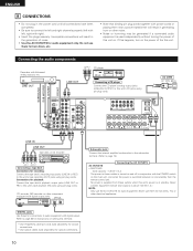
... in generating hum or other noise. • Noise or humming may be generated if a connected audio equipment is used independently without turning the power of this unit on. If this happens, turn on setting this terminal. • Use 75 Ω/ohms cable pin cords (sold separately)... with 6-channel analog outputs, etc. Connecting the audio components Decoders with digital output jacks. DIGITAL jacks Use these outlets when this unit's power is switched between on and off in the generation of the this unit's tape playback (IN) jacks using pin plug cords. Incomplete connections...
... in generating hum or other noise. • Noise or humming may be generated if a connected audio equipment is used independently without turning the power of this unit on. If this happens, turn on setting this terminal. • Use 75 Ω/ohms cable pin cords (sold separately)... with 6-channel analog outputs, etc. Connecting the audio components Decoders with digital output jacks. DIGITAL jacks Use these outlets when this unit's power is switched between on and off in the generation of the this unit's tape playback (IN) jacks using pin plug cords. Incomplete connections...
Owners Manual
Page 15
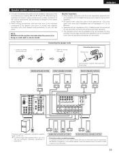
NOTE: NEVER touch the speaker terminals when the power is on the screen may be connected for long periods of time at the same time, since use as front speakers. • Be careful when ...
NOTE: NEVER touch the speaker terminals when the power is on the screen may be connected for long periods of time at the same time, since use as front speakers. • Be careful when ...
Owners Manual
Page 16
...played for example speakers with the wiring or the ventilation around the unit, switch off the power and contact a DENON service center. Improve the ventilation condition around the set 's power, wait for the unit to protect the speakers under circumstances such as when the output of... the power amplifier is inadvertently short-circuited and a large current flows, when the temperature surrounding the unit ...
...played for example speakers with the wiring or the ventilation around the unit, switch off the power and contact a DENON service center. Improve the ventilation condition around the set 's power, wait for the unit to protect the speakers under circumstances such as when the output of... the power amplifier is inadvertently short-circuited and a large current flows, when the temperature surrounding the unit ...

Owners Manual
Page 19
... for the front speakers, "Large" cannot be finished at any time. NOTE: Press the SYSTEM SETUP button again to finish system set up . Press the Power ON/STANDBY switch (button). (Main unit) (Remote control unit) 4 Press the SYSTEM SETUP button to enter the setting. *SYSTEM SET UP NOTE: Please ...the slide switch on the remote control unit. 5 Press the ENTER or (down ) button to switch to turn the power on and off from the remote control unit. 3 Turn on the power. ENGLISH Before setting up the system 1 Refer to "CONNECTIONS" (pages 10 to 16) and check that point are ...
... for the front speakers, "Large" cannot be finished at any time. NOTE: Press the SYSTEM SETUP button again to finish system set up . Press the Power ON/STANDBY switch (button). (Main unit) (Remote control unit) 4 Press the SYSTEM SETUP button to enter the setting. *SYSTEM SET UP NOTE: Please ...the slide switch on the remote control unit. 5 Press the ENTER or (down ) button to switch to turn the power on and off from the remote control unit. 3 Turn on the power. ENGLISH Before setting up the system 1 Refer to "CONNECTIONS" (pages 10 to 16) and check that point are ...
Owners Manual
Page 29
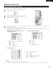
... MODE : Switch between decks A and B SHIFT : Switch preset channel range CHANNEL : Preset channel +, - up /down TUNING : Frequency +, - 11 REMOTE CONTROL UNIT Operating DENON audio components • Turn on the power of components may not be operated. (CD, CDR/MD or Tape deck) 1 3 ENGLISH 3 2 3 Operate the audio component. • For details, refer to...
... MODE : Switch between decks A and B SHIFT : Switch preset channel range CHANNEL : Preset channel +, - up /down TUNING : Frequency +, - 11 REMOTE CONTROL UNIT Operating DENON audio components • Turn on the power of components may not be operated. (CD, CDR/MD or Tape deck) 1 3 ENGLISH 3 2 3 Operate the audio component. • For details, refer to...
Owners Manual
Page 31
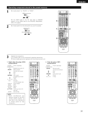
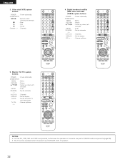
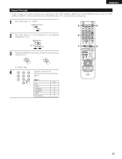
Video disc player (VDP) system buttons POWER : Power on remote control for the DVD/VDP, DBS/CABLE, 3 VCR or TV position. 2 Set mode switch 2 to the component you want to operate. 1 3 ENGLISH 3 2 3 Operate ... VIDEO side for that component. 2. Some models cannot be operated with this remote control unit. 1. Digital video disc player (DVD) system buttons POWER : Power on/standby (ON/SOURCE) OFF : DENON DVD power off 6,7 : Manual search (forward and reverse) 2 : Stop 1 : Play 8,9 : Auto search (to beginning of track) 3 : Pause 0 ~ 9, +10 : 10 key skip + : Disc skip (for...
Video disc player (VDP) system buttons POWER : Power on remote control for the DVD/VDP, DBS/CABLE, 3 VCR or TV position. 2 Set mode switch 2 to the component you want to operate. 1 3 ENGLISH 3 2 3 Operate ... VIDEO side for that component. 2. Some models cannot be operated with this remote control unit. 1. Digital video disc player (DVD) system buttons POWER : Power on/standby (ON/SOURCE) OFF : DENON DVD power off 6,7 : Manual search (forward and reverse) 2 : Stop 1 : Play 8,9 : Auto search (to beginning of track) 3 : Pause 0 ~ 9, +10 : 10 key skip + : Disc skip (for...
Owners Manual
Page 32
...TV (TV) system buttons POWER : Power on /standby (ON/SOURCE) 6,7 : Manual search (forward and reverse) 2 : Stop 1 : Play 3 : Pause Channel +, - : Channels 4. ENGLISH 3. NOTES: • For this CD, CDR, MD and TAPE components, buttons can be operated in the same way as for DENON audio components (page 29...). • The TV can be operated when the switch is at DVD/VDP, VCR, TV position. 32 Video deck (VCR) system buttons POWER : Power on /standby (ON/SOURCE) MENU : Menu RETURN : Return ...
...TV (TV) system buttons POWER : Power on /standby (ON/SOURCE) 6,7 : Manual search (forward and reverse) 2 : Stop 1 : Play 3 : Pause Channel +, - : Channels 4. ENGLISH 3. NOTES: • For this CD, CDR, MD and TAPE components, buttons can be operated in the same way as for DENON audio components (page 29...). • The TV can be operated when the switch is at DVD/VDP, VCR, TV position. 32 Video deck (VCR) system buttons POWER : Power on /standby (ON/SOURCE) MENU : Menu RETURN : Return ...
Owners Manual
Page 33
... set . 1 Set mode switch 1 to "VIDEO". 3 3 2 Set mode switch 2 to the component to be registered (DBS/CABLE or TV). 4 3 Press the DVD/VDP power button and the TV power button at the same time. 1 2 • Indicator flash. 4 1 2 3 4 5 6 7 8 9 0 Input the number of the component you to operate the PLAY, STOP, MANUAL SEARCH and...
... set . 1 Set mode switch 1 to "VIDEO". 3 3 2 Set mode switch 2 to the component to be registered (DBS/CABLE or TV). 4 3 Press the DVD/VDP power button and the TV power button at the same time. 1 2 • Indicator flash. 4 1 2 3 4 5 6 7 8 9 0 Input the number of the component you to operate the PLAY, STOP, MANUAL SEARCH and...
Owners Manual
Page 34
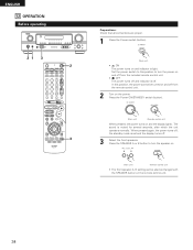
...turn the speaker on. (Main unit) (Remote control unit) • The front speaker A, B setting can be also be turned on the power. When pressed again, the power turns off, the standby mode is light. ENGLISH 12 OPERATION Before operating 21 3 2 3 Preparations: Check that all connections are proper. 1 ...Press the Power switch (button). (Main unit) • ¢ ON The power turns on and the display lights. In this position to turn the power on and off from the remote control unit. 2 Turn on and off from the...
...turn the speaker on. (Main unit) (Remote control unit) • The front speaker A, B setting can be also be turned on the power. When pressed again, the power turns off, the standby mode is light. ENGLISH 12 OPERATION Before operating 21 3 2 3 Preparations: Check that all connections are proper. 1 ...Press the Power switch (button). (Main unit) • ¢ ON The power turns on and the display lights. In this position to turn the power on and off from the remote control unit. 2 Turn on and off from the...

Owners Manual
Page 36
... to the component's manual. 5 Adjust the volume. DIGITAL ANALOG DIGITAL DIGITAL ANALOG The DIGITAL indicator lights when digital signals are correct and whether the component's power is pressed. Example: Stereo (Main unit) To select the surround mode while adjusting the surround parameters, tone defeat or tone control, press the surround mode...
... to the component's manual. 5 Adjust the volume. DIGITAL ANALOG DIGITAL DIGITAL ANALOG The DIGITAL indicator lights when digital signals are correct and whether the component's power is pressed. Example: Stereo (Main unit) To select the surround mode while adjusting the surround parameters, tone defeat or tone control, press the surround mode...
Owners Manual
Page 48
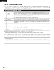
... steering effects, and works with any stereo program source. 2 MONO MOVIE (NOTE 1) 3 ROCK ARENA 4 JAZZ CLUB 5 VIDEO GAME 6 MATRIX Select this to achieve a more realistic, powerful sound. Select this when watching monaural movies for a greater sense of a live house with reflected sounds coming from all speaker surround sound, but without worrying...
... steering effects, and works with any stereo program source. 2 MONO MOVIE (NOTE 1) 3 ROCK ARENA 4 JAZZ CLUB 5 VIDEO GAME 6 MATRIX Select this to achieve a more realistic, powerful sound. Select this when watching monaural movies for a greater sense of a live house with reflected sounds coming from all speaker surround sound, but without worrying...
Owners Manual
Page 53
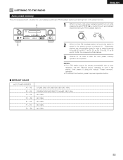
... unit is equipped with a function for automatically searching for FM broadcast stations and storing them in the preset memory. 1 1 When the main unit's power operation switch turn on while pressing the set's PRESET • (+) button the unit automatically begins searching for a maximum of 56 stations. 3 Channel ... auto preset memory operation is stored in the station, then preset it using the manual "Preset memory" operation. • To interrupt this function, press the power operation button. 2 DEFAULT VALUE AUTO TUNER PRESETS A1 ~ A8 B1 ~ B8 C1 ~ C8 D1 ~ D8 E1 ~ E8 F1 ~ F8 G1 ~ ...
... unit is equipped with a function for automatically searching for FM broadcast stations and storing them in the preset memory. 1 1 When the main unit's power operation switch turn on while pressing the set's PRESET • (+) button the unit automatically begins searching for a maximum of 56 stations. 3 Channel ... auto preset memory operation is stored in the station, then preset it using the manual "Preset memory" operation. • To interrupt this function, press the power operation button. 2 DEFAULT VALUE AUTO TUNER PRESETS A1 ~ A8 B1 ~ B8 C1 ~ C8 D1 ~ D8 E1 ~ E8 F1 ~ F8 G1 ~ ...


