
Owners Manual
Page 5
...-Cooling Assembly 35 Prerequisites 35 Procedure 35 Replacing the Thermal-Cooling Assembly 36 Procedure 36 Postrequisites 36 Removing the Power-Adapter Port 37 Prerequisites 37 Procedure 37 Replacing the Power-Adapter Port 38 Procedure 38 Postrequisites 38 Removing the I/O Board 39 Prerequisites 39 Procedure 39 Replacing the I/O Board 41 Procedure 41 Postrequisites...
...-Cooling Assembly 35 Prerequisites 35 Procedure 35 Replacing the Thermal-Cooling Assembly 36 Procedure 36 Postrequisites 36 Removing the Power-Adapter Port 37 Prerequisites 37 Procedure 37 Replacing the Power-Adapter Port 38 Procedure 38 Postrequisites 38 Removing the I/O Board 39 Prerequisites 39 Procedure 39 Replacing the I/O Board 41 Procedure 41 Postrequisites...

Owners Manual
Page 8
..., working inside your computer, and protecting against electrostatic discharge. When disconnecting cables, keep them by touching an unpainted metal surface, such as the metal at dell.com/regulatory_compliance. When connecting cables, make sure that the ports and connectors are correctly oriented and aligned.
..., working inside your computer, and protecting against electrostatic discharge. When disconnecting cables, keep them by touching an unpainted metal surface, such as the metal at dell.com/regulatory_compliance. When connecting cables, make sure that the ports and connectors are correctly oriented and aligned.
Owners Manual
Page 37
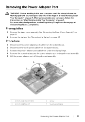
...information that secures the power-adapter port to the palm-rest assembly. 5 Lift the power-adapter port off the palm-rest assembly. 2 1 3 4 1 power-adapter port cable 3 power-adapter port 2 screw 4 touch-panel cable Removing the Power-Adapter Port | 37 See "Removing the Base...-Cover Assembly" on page 16. Prerequisites 1 Remove the base-cover assembly. For more safety best practices, see the Regulatory Compliance home page at dell.com/...
...information that secures the power-adapter port to the palm-rest assembly. 5 Lift the power-adapter port off the palm-rest assembly. 2 1 3 4 1 power-adapter port cable 3 power-adapter port 2 screw 4 touch-panel cable Removing the Power-Adapter Port | 37 See "Removing the Base...-Cover Assembly" on page 16. Prerequisites 1 Remove the base-cover assembly. For more safety best practices, see the Regulatory Compliance home page at dell.com/...

Owners Manual
Page 38
.... 4 Connect the touch-panel cable to the system board. 5 Connect power-adapter port cable to the system board. For more safety best practices, see the Regulatory Compliance home page at dell.com/regulatory_compliance. Postrequisites 1 Replace the battery. See "Replacing the Battery" on page 12.... 38 | Replacing the Power-Adapter Port Procedure 1 Align the screw hole on the power-adapter port with the screw hole on the palm-rest...
.... 4 Connect the touch-panel cable to the system board. 5 Connect power-adapter port cable to the system board. For more safety best practices, see the Regulatory Compliance home page at dell.com/regulatory_compliance. Postrequisites 1 Replace the battery. See "Replacing the Battery" on page 12.... 38 | Replacing the Power-Adapter Port Procedure 1 Align the screw hole on the power-adapter port with the screw hole on the palm-rest...
Owners Manual
Page 46
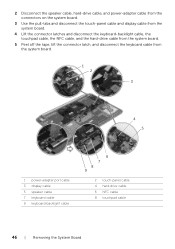
...-drive cable from the system board. 5 Peel off the tape, lift the connector latch, and disconnect the keyboard cable from the system board. 1 2 3 4 5 1 power-adapter port cable 3 display cable 5 speaker cable 7 keyboard cable 9 keyboard-backlight cable 6 7 8 9 2 touch-panel cable 4 hard-drive cable 6 NFC cable 8 touchpad cable 46 | Removing the System Board
...-drive cable from the system board. 5 Peel off the tape, lift the connector latch, and disconnect the keyboard cable from the system board. 1 2 3 4 5 1 power-adapter port cable 3 display cable 5 speaker cable 7 keyboard cable 9 keyboard-backlight cable 6 7 8 9 2 touch-panel cable 4 hard-drive cable 6 NFC cable 8 touchpad cable 46 | Removing the System Board

Owners Manual
Page 48
For more safety best practices, see the Regulatory Compliance home page at dell.com/regulatory_compliance. See "Replacing the Fans" on page 36. 4 Replace the fan. See "Replacing the Thermal-Cooling Assembly" on page 34. 5 Replace the battery. See "... "After Working Inside Your Computer" on the connector latches to secure the cables. 8 Connect the speaker cable, hard-drive cable, touch-panel cable, power-adapter port cable, and display cable to the system board. Procedure CAUTION: Make sure that secure the system board to the palm-rest assembly. 5 Slide the keyboard...
For more safety best practices, see the Regulatory Compliance home page at dell.com/regulatory_compliance. See "Replacing the Fans" on page 36. 4 Replace the fan. See "Replacing the Thermal-Cooling Assembly" on page 34. 5 Replace the battery. See "... "After Working Inside Your Computer" on the connector latches to secure the cables. 8 Connect the speaker cable, hard-drive cable, touch-panel cable, power-adapter port cable, and display cable to the system board. Procedure CAUTION: Make sure that secure the system board to the palm-rest assembly. 5 Slide the keyboard...

Owners Manual
Page 59
...Assembly" on page 44. 14 Remove the keyboard. See "Removing the Fans" on page 30. 8 Remove the fans. See "Removing the Power-Adapter Port" on page 37. 11 Remove the I /O Board" on page 39. 12 Remove the memory modules. See "Removing the mSATA Card" on page 33...See "Removing the Keyboard" on page 42. 13 Remove the system board. For more safety best practices, see the Regulatory Compliance home page at dell.com/regulatory_compliance. See "Removing the I /O board. After working inside your computer and follow the instructions in "Before Working Inside Your Computer" on ...
...Assembly" on page 44. 14 Remove the keyboard. See "Removing the Fans" on page 30. 8 Remove the fans. See "Removing the Power-Adapter Port" on page 37. 11 Remove the I /O Board" on page 39. 12 Remove the memory modules. See "Removing the mSATA Card" on page 33...See "Removing the Keyboard" on page 42. 13 Remove the system board. For more safety best practices, see the Regulatory Compliance home page at dell.com/regulatory_compliance. See "Removing the I /O board. After working inside your computer and follow the instructions in "Before Working Inside Your Computer" on ...

Owners Manual
Page 62
... Board" on page 58. See "Replacing the I /O board. See "Replacing the Thermal-Cooling Assembly" on page 41. 5 Replace the power-adapter port. See "Replacing the Wireless Card" on page 23. 13 Replace the battery. See "Replacing the Hard Drive" on page 27. 11 Replace the speakers... Base-Cover Assembly" on page 53. 2 Replace the system board. For more safety best practices, see the Regulatory Compliance home page at dell.com/regulatory_compliance. Postrequisites 1 Replace the keyboard. See "Replacing the Keyboard" on page 12. 62 | Replacing the Palm-Rest Assembly See "Replacing ...
... Board" on page 58. See "Replacing the I /O board. See "Replacing the Thermal-Cooling Assembly" on page 41. 5 Replace the power-adapter port. See "Replacing the Wireless Card" on page 23. 13 Replace the battery. See "Replacing the Hard Drive" on page 27. 11 Replace the speakers... Base-Cover Assembly" on page 53. 2 Replace the system board. For more safety best practices, see the Regulatory Compliance home page at dell.com/regulatory_compliance. Postrequisites 1 Replace the keyboard. See "Replacing the Keyboard" on page 12. 62 | Replacing the Palm-Rest Assembly See "Replacing ...

Specifications
Page 2
System Information Computer model Processor Chipset XPS 9530 • Intel Core i5 (4th generation) • Intel Core i7 (4th generation) Mobile Intel HM87 Express Chipset Memory Connectors Capacities Type Speed Configurations supported Two ... (7.5 mm) to 1600 MHz 8 GB and 16 GB Ports and Connectors External: USB HDMI port Mini DisplayPort Audio Internal: NGFF Mini Card • One USB 2.0 port with PowerShare • Three USB 3.0 ports with PowerShare One HDMI port One Mini DisplayPort One headset (microphone and headphone combo) port One Next Generation Form Factor (NGFF) slot for WLAN...
System Information Computer model Processor Chipset XPS 9530 • Intel Core i5 (4th generation) • Intel Core i7 (4th generation) Mobile Intel HM87 Express Chipset Memory Connectors Capacities Type Speed Configurations supported Two ... (7.5 mm) to 1600 MHz 8 GB and 16 GB Ports and Connectors External: USB HDMI port Mini DisplayPort Audio Internal: NGFF Mini Card • One USB 2.0 port with PowerShare • Three USB 3.0 ports with PowerShare One HDMI port One Mini DisplayPort One headset (microphone and headphone combo) port One Next Generation Form Factor (NGFF) slot for WLAN...

Specifications
Page 3
...; Wireless Display • Near Field Communication (NFC) Intel HD Graphics 4400/4600 GeForce GT 750M System shared memory 2 GB GDDR5 • HDMI port • Mini DisplayPort • Wireless Display (WiDi) Realtek ALC3661 Realtek ALC5505 Two 2 watt 2.5 watt Digital array-microphones Program menus and keyboard shortcut... keys NOTE: To learn about your computer keyboard shortcut keys, see Quick Start Guide at dell.com/support. SATA 6 Gbps One 2.5-inch drive (supports Intel Smart Response Technology) One Solid State Drive (SSD) with Intel ...
...; Wireless Display • Near Field Communication (NFC) Intel HD Graphics 4400/4600 GeForce GT 750M System shared memory 2 GB GDDR5 • HDMI port • Mini DisplayPort • Wireless Display (WiDi) Realtek ALC3661 Realtek ALC5505 Two 2 watt 2.5 watt Digital array-microphones Program menus and keyboard shortcut... keys NOTE: To learn about your computer keyboard shortcut keys, see Quick Start Guide at dell.com/support. SATA 6 Gbps One 2.5-inch drive (supports Intel Smart Response Technology) One Solid State Drive (SSD) with Intel ...


