Setup and Specifications
Page 3
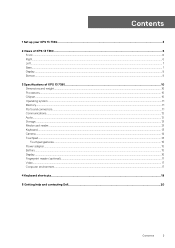
Contents 1 Set up your XPS 13 7390...4 2 Views of XPS 13 7390...6 Front...6 Right...6 Left...7 Base...7 Display...8 Bottom...9 3 Specifications of XPS 13 7390...10 Dimensions and weight...10 Processors...10 Chipset...10 Operating system...11 Memory...11 Ports and connectors...11 Communications...12 Audio...12 Storage...13 Media-card reader...13 Keyboard...13 Camera...14 Touchpad...14 Touchpad gestures...15 Power adapter...15 Battery...
Contents 1 Set up your XPS 13 7390...4 2 Views of XPS 13 7390...6 Front...6 Right...6 Left...7 Base...7 Display...8 Bottom...9 3 Specifications of XPS 13 7390...10 Dimensions and weight...10 Processors...10 Chipset...10 Operating system...11 Memory...11 Ports and connectors...11 Communications...12 Audio...12 Storage...13 Media-card reader...13 Keyboard...13 Camera...14 Touchpad...14 Touchpad gestures...15 Power adapter...15 Battery...
Setup and Specifications
Page 4
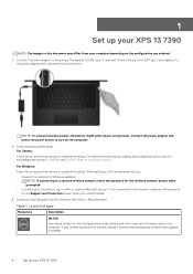
.... 4 Set up your XPS 13 7390 NOTE: The images in with Power Delivery (the USB Type-C port adjacent to the primary Thunderbolt 3 (USB Type-C) port with or create a Microsoft account. 1 Set up your XPS 13 7390 Connect the power adapter to the power-adapter port) and press the power button. Finish operating system setup. Locate Dell apps Resources Description My...
.... 4 Set up your XPS 13 7390 NOTE: The images in with Power Delivery (the USB Type-C port adjacent to the primary Thunderbolt 3 (USB Type-C) port with or create a Microsoft account. 1 Set up your XPS 13 7390 Connect the power adapter to the power-adapter port) and press the power button. Finish operating system setup. Locate Dell apps Resources Description My...
Setup and Specifications
Page 6
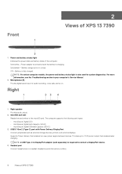
...) is low or critical. Power and battery-status light Indicates the power state and battery state of XPS 13 7390 Microphones (4) Provide digital sound input for system diagnostics. The computer supports the following card types: •...port Connect headphones or a headset (headphone and microphone combo). 6 Views of the computer. Solid white-Power adapter is connected and the battery is charging. USB 3.1 Gen 2 (Type-C) port with Power Delivery/DisplayPort Connect peripherals such as external storage devices, printers, and external displays. Front 2 Views of XPS 13 7390...
...) is low or critical. Power and battery-status light Indicates the power state and battery state of XPS 13 7390 Microphones (4) Provide digital sound input for system diagnostics. The computer supports the following card types: •...port Connect headphones or a headset (headphone and microphone combo). 6 Views of the computer. Solid white-Power adapter is connected and the battery is charging. USB 3.1 Gen 2 (Type-C) port with Power Delivery/DisplayPort Connect peripherals such as external storage devices, printers, and external displays. Front 2 Views of XPS 13 7390...
Setup and Specifications
Page 7
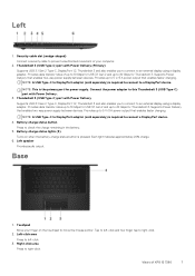
... you to connect to 40 Gbps for Thunderbolt 3. Provides data transfer rates of XPS 13 7390 7 Provides up to 5 V/3 A power output that enables faster charging. NOTE: This is required to this Thunderbolt 3 (USB Type-C) port with Power Delivery. 3. Thunderbolt 3 (USB Type-C) port with Power Delivery (Primary) Supports USB 3.1 Gen 2 Type-C, DisplayPort 1.2, Thunderbolt 3 and also enables...
... you to connect to 40 Gbps for Thunderbolt 3. Provides data transfer rates of XPS 13 7390 7 Provides up to 5 V/3 A power output that enables faster charging. NOTE: This is required to this Thunderbolt 3 (USB Type-C) port with Power Delivery. 3. Thunderbolt 3 (USB Type-C) port with Power Delivery (Primary) Supports USB 3.1 Gen 2 Type-C, DisplayPort 1.2, Thunderbolt 3 and also enables...
Setup and Specifications
Page 11
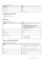
...NOTE: The memory modules are malfunctioning and need to be replaced, a replacement of XPS 13 7390 11 Memory specifications Description Slots Type Speed Maximum memory Minimum memory Configurations supported Ports and connectors Table 6. Chipset(continued) Description DRAM bus width Flash EPROM PCIe bus ...16 GB LPDDR3 at 2133 MHz • Two USB Thunderbolt 3 (Type-C) ports with Power Delivery • One USB 3.1 Gen 2 (Type-C) port with Power Delivery/ DisplayPort One headset (headphone and microphone combo) port DisplayPort (DP) 1.2 support through a USB Type-C connector One microSD-card...
...NOTE: The memory modules are malfunctioning and need to be replaced, a replacement of XPS 13 7390 11 Memory specifications Description Slots Type Speed Maximum memory Minimum memory Configurations supported Ports and connectors Table 6. Chipset(continued) Description DRAM bus width Flash EPROM PCIe bus ...16 GB LPDDR3 at 2133 MHz • Two USB Thunderbolt 3 (Type-C) ports with Power Delivery • One USB 3.1 Gen 2 (Type-C) port with Power Delivery/ DisplayPort One headset (headphone and microphone combo) port DisplayPort (DP) 1.2 support through a USB Type-C connector One microSD-card...
Setup and Specifications
Page 12
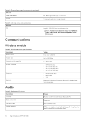
... microphone-in, stereo headphones, and headset combo 12 Specifications of M.2 cards, see the knowledge base article SLN301626. External ports and connectors(continued) External: Power adapter port Security Table 7. Wireless module specifications Description Model number Transfer rate Frequency bands supported Wireless standards Encryption Bluetooth Audio Table 9. Audio...shaped) One M.2 2230/2280 slot for solid-state drive NOTE: To learn more about the features of different types of XPS 13 7390 Table 6. Internal ports and connectors Internal: M.2 Communications Wireless module Table 8.
... microphone-in, stereo headphones, and headset combo 12 Specifications of M.2 cards, see the knowledge base article SLN301626. External ports and connectors(continued) External: Power adapter port Security Table 7. Wireless module specifications Description Model number Transfer rate Frequency bands supported Wireless standards Encryption Bluetooth Audio Table 9. Audio...shaped) One M.2 2230/2280 slot for solid-state drive NOTE: To learn more about the features of different types of XPS 13 7390 Table 6. Internal ports and connectors Internal: M.2 Communications Wireless module Table 8.
Service Manual
Page 4
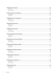
13 Replacing the speakers...28 Procedure...28 Post-requisites...28 14 Removing the coin-cell battery 29 Prerequisites...29 Procedure...29 15 Replacing the coin-cell ... 20 Removing the display assembly 37 Prerequisites...37 Procedure...37 21 Replacing the display assembly 39 Procedure...39 Post-requisites...40 22 Removing the headset port...41 Prerequisites...41 Procedure...41 23 Replacing the headset port...43 Procedure...43 Post-requisites...44 24 Removing the fans...45 Prerequisites...45 Procedure...45 4 Contents
13 Replacing the speakers...28 Procedure...28 Post-requisites...28 14 Removing the coin-cell battery 29 Prerequisites...29 Procedure...29 15 Replacing the coin-cell ... 20 Removing the display assembly 37 Prerequisites...37 Procedure...37 21 Replacing the display assembly 39 Procedure...39 Post-requisites...40 22 Removing the headset port...41 Prerequisites...41 Procedure...41 23 Replacing the headset port...43 Procedure...43 Post-requisites...44 24 Removing the fans...45 Prerequisites...45 Procedure...45 4 Contents
Service Manual
Page 9
...and eject any connector pins. Due to the increased density of the time when damage occurs, it is not covered by Dell is not immediately recognizable. The damage causes an immediate and complete loss of ESD-related failures. Intermittent failures represent approximately 80... the industry pushes for missing or nonfunctional memory. • Intermittent - Unless otherwise noted, each procedure included in ways that the ports and connectors are correctly oriented and aligned. NOTE: Before working inside the computer, replace all power sources before connecting to static damage...
...and eject any connector pins. Due to the increased density of the time when damage occurs, it is not covered by Dell is not immediately recognizable. The damage causes an immediate and complete loss of ESD-related failures. Intermittent failures represent approximately 80... the industry pushes for missing or nonfunctional memory. • Intermittent - Unless otherwise noted, each procedure included in ways that the ports and connectors are correctly oriented and aligned. NOTE: Before working inside the computer, replace all power sources before connecting to static damage...
Service Manual
Page 13
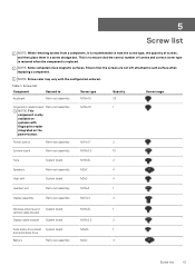
...4x1.7 2 System board Palm-rest assembly M1.6x2.5 10 Fans System board M1.6x3L 2 Speakers Palm-rest assembly M2x2 4 Heat sink System board M2x3 4 Headset port Palm-rest assembly M1.6x3 1 Display assembly Palm-rest assembly M2.5x4 4 Wireless antenna and System board M1.6x3L 1 camera cable bracket Display cable bracket... System board M1.6x2.5 2 Solid-state drive shield System board M2x3L 1 and solid-state drive Battery Palm-rest assembly M2x2 4 Screw list 13 This is only available on systems with the configuration ordered. Table 1.
...4x1.7 2 System board Palm-rest assembly M1.6x2.5 10 Fans System board M1.6x3L 2 Speakers Palm-rest assembly M2x2 4 Heat sink System board M2x3 4 Headset port Palm-rest assembly M1.6x3 1 Display assembly Palm-rest assembly M2.5x4 4 Wireless antenna and System board M1.6x3L 1 camera cable bracket Display cable bracket... System board M1.6x2.5 2 Solid-state drive shield System board M2x3L 1 and solid-state drive Battery Palm-rest assembly M2x2 4 Screw list 13 This is only available on systems with the configuration ordered. Table 1.
Service Manual
Page 41
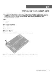
..., see the Regulatory Compliance home page at www.dell.com/regulatory_compliance. Remove the base cover. 2. Remove the battery. Removing the headset port 41 Place the top surface of the computer on a flat and clean surface, then open and close the computer. 22 Removing the headset port NOTE: Before working inside your computer, read...
..., see the Regulatory Compliance home page at www.dell.com/regulatory_compliance. Remove the base cover. 2. Remove the battery. Removing the headset port 41 Place the top surface of the computer on a flat and clean surface, then open and close the computer. 22 Removing the headset port NOTE: Before working inside your computer, read...
Service Manual
Page 42
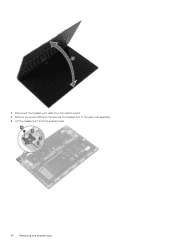
Disconnect the headset-port cable from the system board. 42 Removing the headset port Remove the screw (M1.6x3) that secures the headset port to the palm-rest assembly. 5. 3. Lift the headset port from the system board. 4.
Disconnect the headset-port cable from the system board. 42 Removing the headset port Remove the screw (M1.6x3) that secures the headset port to the palm-rest assembly. 5. 3. Lift the headset port from the system board. 4.
Service Manual
Page 43
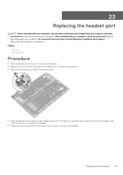
For more safety best practices, see the Regulatory Compliance home page at www.dell.com/regulatory_compliance. Replace the screw (M1.6x3) that secures the headset port to the palm-rest assembly. Replace the two screws (M2.5x4) that secure the left hinge to the palm-rest assembly 3. ...system board. 4. After working inside your computer, follow the steps in Before working inside your computer. Replacing the headset port 43 23 Replacing the headset port NOTE: Before working inside your computer, read the safety information that shipped with your computer and follow the instructions in...
For more safety best practices, see the Regulatory Compliance home page at www.dell.com/regulatory_compliance. Replace the screw (M1.6x3) that secures the headset port to the palm-rest assembly. Replace the two screws (M2.5x4) that secure the left hinge to the palm-rest assembly 3. ...system board. 4. After working inside your computer, follow the steps in Before working inside your computer. Replacing the headset port 43 23 Replacing the headset port NOTE: Before working inside your computer, read the safety information that shipped with your computer and follow the instructions in...
Service Manual
Page 44
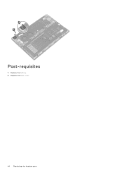
Post-requisites 1. Replace the battery. 2. Replace the base cover. 44 Replacing the headset port
Post-requisites 1. Replace the battery. 2. Replace the base cover. 44 Replacing the headset port
Service Manual
Page 49
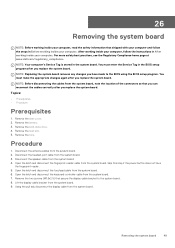
...disconnect the display cable from the system board. 2. For more safety best practices, see the Regulatory Compliance home page at www.dell.com/regulatory_compliance. NOTE: Replacing the system board removes any changes you replace the system board. You must enter the Service Tag in...: • Prerequisites • Procedure Prerequisites 1. You must make the appropriate changes again after you replace the system board. Disconnect the headset-port cable from the system board. 4. Disconnect the speaker cable from the system board. 3. Skip this step if the power button does not ...
...disconnect the display cable from the system board. 2. For more safety best practices, see the Regulatory Compliance home page at www.dell.com/regulatory_compliance. NOTE: Replacing the system board removes any changes you replace the system board. You must enter the Service Tag in...: • Prerequisites • Procedure Prerequisites 1. You must make the appropriate changes again after you replace the system board. Disconnect the headset-port cable from the system board. 4. Disconnect the speaker cable from the system board. 3. Skip this step if the power button does not ...
Service Manual
Page 52
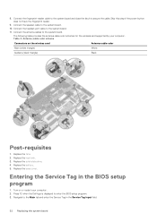
Replace the fans. 2. Replace the battery. 5. Press F2 when the Dell logo is displayed to the system board. Navigate to secure the cable. Connect the antenna cables to enter the BIOS setup program. 3. Antenna-cable color ... (white triangle) White Auxiliary (black triangle) Black Post-requisites 1. Skip this step if the power button does not have the fingerprint reader. 9. Connect the headset-port cable to the system board. 10. Connect the fingerprint-reader cable to the system board and close the latch to the Main tab and enter...
Replace the fans. 2. Replace the battery. 5. Press F2 when the Dell logo is displayed to the system board. Navigate to secure the cable. Connect the antenna cables to enter the BIOS setup program. 3. Antenna-cable color ... (white triangle) White Auxiliary (black triangle) Black Post-requisites 1. Skip this step if the power button does not have the fingerprint reader. 9. Connect the headset-port cable to the system board. 10. Connect the fingerprint-reader cable to the system board and close the latch to the Main tab and enter...
Service Manual
Page 60
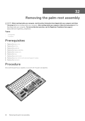
... follow the instructions in Before working inside your computer. For more safety best practices, see the Regulatory Compliance home page at www.dell.com/regulatory_compliance. Topics: • Prerequisites • Procedure Prerequisites 1. Remove the base cover. 2. Remove the fans. 7. After ...working inside your computer, follow the steps in After working inside your computer. Remove the speakers. 4. Remove the headset port. 6. Remove the power button with the palm-rest assembly. 60 Removing the palm-rest assembly Procedure After performing all the pre-...
... follow the instructions in Before working inside your computer. For more safety best practices, see the Regulatory Compliance home page at www.dell.com/regulatory_compliance. Topics: • Prerequisites • Procedure Prerequisites 1. Remove the base cover. 2. Remove the fans. 7. After ...working inside your computer, follow the steps in After working inside your computer. Remove the speakers. 4. Remove the headset port. 6. Remove the power button with the palm-rest assembly. 60 Removing the palm-rest assembly Procedure After performing all the pre-...
Service Manual
Page 61
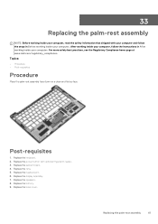
... working inside your computer. Replacing the palm-rest assembly 61 Post-requisites 1. Replace the fans. 5. Replace the headset port. 6. For more safety best practices, see the Regulatory Compliance home page at www.dell.com/regulatory_compliance. Replace the battery. 9. After working inside your computer, follow the steps in After working inside your computer...
... working inside your computer. Replacing the palm-rest assembly 61 Post-requisites 1. Replace the fans. 5. Replace the headset port. 6. For more safety best practices, see the Regulatory Compliance home page at www.dell.com/regulatory_compliance. Replace the battery. 9. After working inside your computer, follow the steps in After working inside your computer...
Service Manual
Page 66
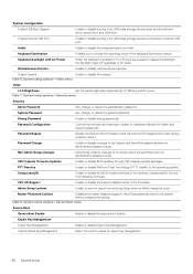
... UEFI Capsule Firmware Updates Enable or disable BIOS updates through UEFI capsule update packages. Hard Disk passwords need to external USB port. Expert Key Management Expert Key Management Enable or disable Expert Key Management. Non-Admin Setup Changes Determines whether changes to the...for Admin and System passwords. System Configuration Enable USB Boot Support Enable or disable booting from Absolute Software. Enable External USB Port Enable or disable booting from entering Setup when an Admin Password is set . Password Configuration Control the minimum and maximum number...
... UEFI Capsule Firmware Updates Enable or disable BIOS updates through UEFI capsule update packages. Hard Disk passwords need to external USB port. Expert Key Management Expert Key Management Enable or disable Expert Key Management. Non-Admin Setup Changes Determines whether changes to the...for Admin and System passwords. System Configuration Enable USB Boot Support Enable or disable booting from Absolute Software. Enable External USB Port Enable or disable booting from entering Setup when an Admin Password is set . Password Configuration Control the minimum and maximum number...


