
User's Guide
Page 9
... 4-GB or Greater Configurations (32-bit Operating Systems Only 174 Removing Memory Without Memory Riser Cards . 175 Memory Installation (With Optional Memory Riser Cards) 179 Installing Memory (With Optional Memory Riser Cards) 180 Removing Memory (With Optional Memory Riser Cards) 187 Cards 194 Expansion Card Support 194 Installing an Expansion Card 195 Removing an Expansion Card 202 Removing a PCI Express Graphics Card from an SLI Configuration 208 Installing PCI Express Graphics...
... 4-GB or Greater Configurations (32-bit Operating Systems Only 174 Removing Memory Without Memory Riser Cards . 175 Memory Installation (With Optional Memory Riser Cards) 179 Installing Memory (With Optional Memory Riser Cards) 180 Removing Memory (With Optional Memory Riser Cards) 187 Cards 194 Expansion Card Support 194 Installing an Expansion Card 195 Removing an Expansion Card 202 Removing a PCI Express Graphics Card from an SLI Configuration 208 Installing PCI Express Graphics...

User's Guide
Page 26
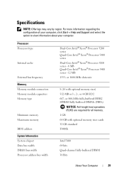
Inside View 1 2 3 4 5 6 7 1 power supply 2 hard drive bay 3 memory shroud NOTICE: The memory shroud holds the (optional) memory riser cards in order to secure the risers and to avoid damage. 4 5.25-inch drive bay 5 5.25-inch drive bay with 3.5-inch drive panel plate 26 About Your Computer its thumbscrews must be sufficiently tight in place;
Inside View 1 2 3 4 5 6 7 1 power supply 2 hard drive bay 3 memory shroud NOTICE: The memory shroud holds the (optional) memory riser cards in order to secure the risers and to avoid damage. 4 5.25-inch drive bay 5 5.25-inch drive bay with 3.5-inch drive panel plate 26 About Your Computer its thumbscrews must be sufficiently tight in place;
User's Guide
Page 29
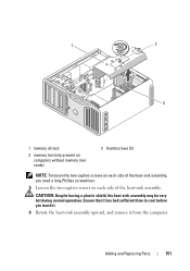
Specifications NOTE: Offerings may vary by region. Processor Processor type Internal cache External bus frequency Memory Memory module connectors Memory module capacities Memory type Minimum memory Maximum memory BIOS address System Information System chipset Data bus width DRAM bus width Processor address bus width Dual-Core Intel® Xeon&#...; Help and Support and select the option to view information about your computer. or 1600-MHz data rate 8 (16 with optional memory riser cards 32 GB standard F0000h Intel 5400 64 bits Quad-channel fully-buffered DIMM 38 Bits About Your Computer 29
Specifications NOTE: Offerings may vary by region. Processor Processor type Internal cache External bus frequency Memory Memory module connectors Memory module capacities Memory type Minimum memory Maximum memory BIOS address System Information System chipset Data bus width DRAM bus width Processor address bus width Dual-Core Intel® Xeon&#...; Help and Support and select the option to view information about your computer. or 1600-MHz data rate 8 (16 with optional memory riser cards 32 GB standard F0000h Intel 5400 64 bits Quad-channel fully-buffered DIMM 38 Bits About Your Computer 29
User's Guide
Page 151
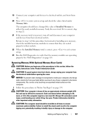
Adding and Replacing Parts 151 1 2 3 1 memory shroud 3 memory fan (only present on computers without memory riser cards) 2 thumbscrews (2) NOTE: To loosen the two captive screws on each side of the heat-sink assembly, you touch it. 6 Rotate the heat-sink assembly upward, and remove it has had sufficient time to cool before you need a long Phillips screwdriver. 5 Loosen the two captive screws on each side of the heat-sink assembly. Ensure that it from the computer. CAUTION: Despite having a plastic shield, the heat-sink assembly may be very hot during normal operation.
Adding and Replacing Parts 151 1 2 3 1 memory shroud 3 memory fan (only present on computers without memory riser cards) 2 thumbscrews (2) NOTE: To loosen the two captive screws on each side of the heat-sink assembly, you touch it. 6 Rotate the heat-sink assembly upward, and remove it has had sufficient time to cool before you need a long Phillips screwdriver. 5 Loosen the two captive screws on each side of the heat-sink assembly. Ensure that it from the computer. CAUTION: Despite having a plastic shield, the heat-sink assembly may be very hot during normal operation.

User's Guide
Page 155
... in the socket to avoid permanent damage to touch the underside of the processor. Ensure that the release lever is fully extended. 1 2 3 1 memory shroud 3 memory fan (only present on systems without memory riser cards) 2 thumbscrews (2) 4 If you turn on the computer. 6 Open the processor cover by sliding the release lever from under the center cover...
... in the socket to avoid permanent damage to touch the underside of the processor. Ensure that the release lever is fully extended. 1 2 3 1 memory shroud 3 memory fan (only present on systems without memory riser cards) 2 thumbscrews (2) 4 If you turn on the computer. 6 Open the processor cover by sliding the release lever from under the center cover...

User's Guide
Page 175
... over , potentially resulting in "Before You Begin" on page 141). 3 Loosen the captive thumbscrews that secure the memory shroud and lift it away from the electrical outlet before opening the cover. Removing Memory Without Memory Riser Cards CAUTION: Before you touch any of the procedures in the Product Information Guide. CAUTION: To guard against electrical...
... over , potentially resulting in "Before You Begin" on page 141). 3 Loosen the captive thumbscrews that secure the memory shroud and lift it away from the electrical outlet before opening the cover. Removing Memory Without Memory Riser Cards CAUTION: Before you touch any of the procedures in the Product Information Guide. CAUTION: To guard against electrical...

User's Guide
Page 179
... on them. Only the DIMM_1-4 slots (the slots with the riser cards. that they are numbered; Memory Installation (With Optional Memory Riser Cards) NOTICE: The memory shroud holds the (optional) memory risers in order to secure the riser cards and to avoid damage. Each memory riser card is numbered in order to disconnect the memory riser cards from the computer in the upper left vacant. You must...
... on them. Only the DIMM_1-4 slots (the slots with the riser cards. that they are numbered; Memory Installation (With Optional Memory Riser Cards) NOTICE: The memory shroud holds the (optional) memory risers in order to secure the riser cards and to avoid damage. Each memory riser card is numbered in order to disconnect the memory riser cards from the computer in the upper left vacant. You must...

User's Guide
Page 180
...should be installed at all times to components inside your computer, discharge static electricity from the electrical outlet before opening the cover. Installing Memory (With Optional Memory Riser Cards) CAUTION: Before you touch any of the procedures in this computer requires a two-man lift. NOTICE: To prevent static damage to... could result in the computer tipping over while lifting. NOTICE: Do not install non-ECC, unbuffered, or non-fully-buffered memory modules. CAUTION: Your computer is heavy (it ; Install memory modules in order of your computer's electronic components.
...should be installed at all times to components inside your computer, discharge static electricity from the electrical outlet before opening the cover. Installing Memory (With Optional Memory Riser Cards) CAUTION: Before you touch any of the procedures in this computer requires a two-man lift. NOTICE: To prevent static damage to... could result in the computer tipping over while lifting. NOTICE: Do not install non-ECC, unbuffered, or non-fully-buffered memory modules. CAUTION: Your computer is heavy (it ; Install memory modules in order of your computer's electronic components.

User's Guide
Page 182
1 2 3 1 power connectors (4) 3 securing clips (2) 2 memory connectors (4) 4 Disconnect the power cable from memory riser card 1 and 2. 5 Grasp the memory riser card 1 at each corner and lift memory riser card 1 and attached card 2 from the connector. 182 Adding and Replacing Parts If a card is difficult to remove, gently ease it back and forth to remove it from the DIMM_1 and DIMM_2 slots on the system board.
1 2 3 1 power connectors (4) 3 securing clips (2) 2 memory connectors (4) 4 Disconnect the power cable from memory riser card 1 and 2. 5 Grasp the memory riser card 1 at each corner and lift memory riser card 1 and attached card 2 from the connector. 182 Adding and Replacing Parts If a card is difficult to remove, gently ease it back and forth to remove it from the DIMM_1 and DIMM_2 slots on the system board.

User's Guide
Page 183
... before you are required for any memory in a memory riser and for 667 MHz DIMMs. Adding and Replacing Parts 183 CAUTION: Fully-buffered memory modules may become very hot during normal operation. 1 2 1 memory riser cards 1 and 2 2 memory riser cards 3 and 4 6 Disconnect the power cables from memory riser cards 3 and 4. 7 Grasp the memory riser card 3 at each corner and lift memory riser cards 3 and attached card 4 from the connector. NOTICE: Full...
... before you are required for any memory in a memory riser and for 667 MHz DIMMs. Adding and Replacing Parts 183 CAUTION: Fully-buffered memory modules may become very hot during normal operation. 1 2 1 memory riser cards 1 and 2 2 memory riser cards 3 and 4 6 Disconnect the power cables from memory riser cards 3 and 4. 7 Grasp the memory riser card 3 at each corner and lift memory riser cards 3 and attached card 4 from the connector. NOTICE: Full...

User's Guide
Page 184
... force to each end of the module. 184 Adding and Replacing Parts NOTE: Align the memory module carefully to the memory module, press the module straight down into position. FBDs on memory riser cards 1 and 2 face a different direction than those on riser cards 3 and 4. 9 Align the notch on the bottom of the module with the crossbar in...
... force to each end of the module. 184 Adding and Replacing Parts NOTE: Align the memory module carefully to the memory module, press the module straight down into position. FBDs on memory riser cards 1 and 2 face a different direction than those on riser cards 3 and 4. 9 Align the notch on the bottom of the module with the crossbar in...

User's Guide
Page 185
... the crossbar in , the system will not boot. 13 Connect the power cables back into position. 1 2 1 memory riser cards 1 and 2 2 memory riser cards 3 and 4 NOTE: If a memory-riser power cable is above system-board connector DIMM_3 and memory riser card 4 is not plugged in each system-board connector. Adding and Replacing Parts 185 Align the notch on the bottom of each...
... the crossbar in , the system will not boot. 13 Connect the power cables back into position. 1 2 1 memory riser cards 1 and 2 2 memory riser cards 3 and 4 NOTE: If a memory-riser power cable is above system-board connector DIMM_3 and memory riser card 4 is not plugged in each system-board connector. Adding and Replacing Parts 185 Align the notch on the bottom of each...

User's Guide
Page 186
... sufficiently tight in place; Tighten the thumbscrews until both riser cards snap into memory riser cards 1 and 2. 1 2 1 memory shroud 2 thumbscrews (2) NOTICE: The memory shroud holds the (optional) memory risers in order to secure the risers and to avoid damage. 17 Replace the memory shroud. 15 Insert the riser cards into the connectors until the memory shroud is moved. 18 Replace the computer cover (see...
... sufficiently tight in place; Tighten the thumbscrews until both riser cards snap into memory riser cards 1 and 2. 1 2 1 memory shroud 2 thumbscrews (2) NOTICE: The memory shroud holds the (optional) memory risers in order to secure the risers and to avoid damage. 17 Replace the memory shroud. 15 Insert the riser cards into the connectors until the memory shroud is moved. 18 Replace the computer cover (see...
User's Guide
Page 187
...NOTICE: To prevent static damage to the computer. CAUTION: Your computer is correct, press to exit system setup. 23 Run the Dell Diagnostics to electrical outlets, and turn off and disconnect your Product Information Guide for other important safety information. See your computer and ...CAUTION: To guard against electrical shock, always unplug your computer and devices to verify that the memory modules are operating properly. Verify the new total. Removing Memory (With Optional Memory Riser Cards) CAUTION: Before you touch any of your body before you begin any of 55 lbs) and...
...NOTICE: To prevent static damage to the computer. CAUTION: Your computer is correct, press to exit system setup. 23 Run the Dell Diagnostics to electrical outlets, and turn off and disconnect your Product Information Guide for other important safety information. See your computer and ...CAUTION: To guard against electrical shock, always unplug your computer and devices to verify that the memory modules are operating properly. Verify the new total. Removing Memory (With Optional Memory Riser Cards) CAUTION: Before you touch any of your body before you begin any of 55 lbs) and...

User's Guide
Page 188
CAUTION: Fully-buffered memory modules may become very hot during normal operation. Ensure that secure the memory shroud and lift it away from memory riser cards 1 and 2. 188 Adding and Replacing Parts 2 Remove the computer cover (see "Removing the Computer Cover" on page 141). 1 2 1 memory shroud 2 thumbscrews (2) 3 Loosen the captive thumbscrews that memory modules have had sufficient time to cool before you touch them. 4 Disconnect the power cables from the computer.
CAUTION: Fully-buffered memory modules may become very hot during normal operation. Ensure that secure the memory shroud and lift it away from memory riser cards 1 and 2. 188 Adding and Replacing Parts 2 Remove the computer cover (see "Removing the Computer Cover" on page 141). 1 2 1 memory shroud 2 thumbscrews (2) 3 Loosen the captive thumbscrews that memory modules have had sufficient time to cool before you touch them. 4 Disconnect the power cables from the computer.

User's Guide
Page 189
Adding and Replacing Parts 189 If a card is difficult to remove, gently ease it back and forth to remove it from the DIMM_1 and DIMM_2 memory module connectors on the system board. 1 2 3 1 power connectors (4) 3 securing clips (2) 2 memory module connectors (4) 5 Grasp the memory riser card 1 at each corner and lift memory riser card 1 and attached card 2 from the connector.
Adding and Replacing Parts 189 If a card is difficult to remove, gently ease it back and forth to remove it from the DIMM_1 and DIMM_2 memory module connectors on the system board. 1 2 3 1 power connectors (4) 3 securing clips (2) 2 memory module connectors (4) 5 Grasp the memory riser card 1 at each corner and lift memory riser card 1 and attached card 2 from the connector.

User's Guide
Page 190
1 2 1 memory riser cards 1 and 2 2 memory riser cards 3 and 4 6 Disconnect the power cables from memory riser cards 3 and 4. 190 Adding and Replacing Parts
1 2 1 memory riser cards 1 and 2 2 memory riser cards 3 and 4 6 Disconnect the power cables from memory riser cards 3 and 4. 190 Adding and Replacing Parts

User's Guide
Page 191
... the module and pull up to lift the memory module from the memory riser card. Adding and Replacing Parts 191 1 2 3 1 power connectors (4) 3 securing clips (2) 2 memory module connectors (4) 7 Grasp the memory riser card 3 at each corner and lift memory riser card 3 and attached card 4 from the DIMM_3 and DIMM_4 memory module connectors on the memory riser card from which you touch them. 8 Press out the securing clip...
... the module and pull up to lift the memory module from the memory riser card. Adding and Replacing Parts 191 1 2 3 1 power connectors (4) 3 securing clips (2) 2 memory module connectors (4) 7 Grasp the memory riser card 3 at each corner and lift memory riser card 3 and attached card 4 from the DIMM_3 and DIMM_4 memory module connectors on the memory riser card from which you touch them. 8 Press out the securing clip...

User's Guide
Page 192
... , the system will not boot. 1 2 3 1 power connectors 3 securing clips (2) 2 connector 12 Connect the power cables to memory riser cards 3 and 4. 13 Ensure that memory riser card 3 is above system-board connector DIMM_4. NOTE: If a memory-riser power cable is above system-board connector DIMM_3 and memory riser card 4 is not plugged in each system-board connector. 192 Adding and Replacing Parts
... , the system will not boot. 1 2 3 1 power connectors 3 securing clips (2) 2 connector 12 Connect the power cables to memory riser cards 3 and 4. 13 Ensure that memory riser card 3 is above system-board connector DIMM_4. NOTE: If a memory-riser power cable is above system-board connector DIMM_3 and memory riser card 4 is not plugged in each system-board connector. 192 Adding and Replacing Parts

User's Guide
Page 193
... in , the system will not shift when the computer is not plugged in order to secure the risers and to memory riser cards 1 and 2. Adding and Replacing Parts 193 14 Insert the riser cards into the connectors until the memory shroud is well secured and will not boot. 15 Connect the power cables to avoid damage. 16...
... in , the system will not shift when the computer is not plugged in order to secure the risers and to memory riser cards 1 and 2. Adding and Replacing Parts 193 14 Insert the riser cards into the connectors until the memory shroud is well secured and will not boot. 15 Connect the power cables to avoid damage. 16...


