
Owner's Manual
Page 3
......13 Removing the Hard Drive...13 Installing the Hard Drive ...15 Removing the Air Tunnel...15 Installing the Air Tunnel...15 Removing the Memory...15 Installing the Memory...16 Removing the Coin-Cell Battery...16 Installing the Coin-Cell Battery...16 Removing the Heat Sink...16 Installing the Heat Sink...17 Removing...
......13 Removing the Hard Drive...13 Installing the Hard Drive ...15 Removing the Air Tunnel...15 Installing the Air Tunnel...15 Removing the Memory...15 Installing the Memory...16 Removing the Coin-Cell Battery...16 Installing the Coin-Cell Battery...16 Removing the Heat Sink...16 Installing the Heat Sink...17 Removing...
Owner's Manual
Page 4
... Removing the Speaker...30 Installing the Speaker...31 Removing the System Board...31 Installing the System Board...34 System Board Components...34 3 Additional Information...37 Memory Module Guidelines...37 Power Supply Unit (PSU) Lock...37 4 System Setup...39 Boot Sequence...39 Navigation Keys...39 System Setup Options...40 Updating the BIOS... That Halt Your Computer Completely...54 Errors That Do Not Halt Your Computer...54 Errors That Soft Halt Your Computer...54 7 Technical Specifications...57 8 Contacting Dell...65
... Removing the Speaker...30 Installing the Speaker...31 Removing the System Board...31 Installing the System Board...34 System Board Components...34 3 Additional Information...37 Memory Module Guidelines...37 Power Supply Unit (PSU) Lock...37 4 System Setup...39 Boot Sequence...39 Navigation Keys...39 System Setup Options...40 Updating the BIOS... That Halt Your Computer Completely...54 Errors That Do Not Halt Your Computer...54 Errors That Soft Halt Your Computer...54 7 Technical Specifications...57 8 Contacting Dell...65

Owner's Manual
Page 15
...the hard drive cage and slide it from the computer. 15 Press down on the retention tab on the latches of the memory module, and lift the memory module upwards to remove it clicks into place. 3. Follow the procedures in After Working Inside Your Computer. Connect the hard ...Before Working Inside Your Computer. 2. Install the air tunnel in on the air tunnel and lift it inside the compartment. 2. Removing the Memory 1. Press in the computer chassis. 2. Remove the cover. 3. Install: a) optical drive b) cover 4. Connect the hard drive data cable. 4. Press down on...
...the hard drive cage and slide it from the computer. 15 Press down on the retention tab on the latches of the memory module, and lift the memory module upwards to remove it clicks into place. 3. Follow the procedures in After Working Inside Your Computer. Connect the hard ...Before Working Inside Your Computer. 2. Install the air tunnel in on the air tunnel and lift it inside the compartment. 2. Removing the Memory 1. Press in the computer chassis. 2. Remove the cover. 3. Install: a) optical drive b) cover 4. Connect the hard drive data cable. 4. Press down on...

Owner's Manual
Page 16
Install the cover. 4. Follow the procedures in After Working Inside Your Computer. Install the cover. 4. Remove the cover. 3. Insert the memory module into place and secures it. 3. Press down on the system board. 2. Removing the Coin-Cell Battery 1. Follow the procedures in ...Inside Your Computer. 2. Press the release latch away from the battery to allow the battery to pop-up from the system board. 16 Installing the Memory 1. Installing the Coin-Cell Battery 1. Remove the cover. 3. Lift the coin-cell battery out of the computer. Removing the Heat Sink 1. Place...
Install the cover. 4. Follow the procedures in After Working Inside Your Computer. Install the cover. 4. Remove the cover. 3. Insert the memory module into place and secures it. 3. Press down on the system board. 2. Removing the Coin-Cell Battery 1. Follow the procedures in ...Inside Your Computer. 2. Press the release latch away from the battery to allow the battery to pop-up from the system board. 16 Installing the Memory 1. Installing the Coin-Cell Battery 1. Remove the cover. 3. Lift the coin-cell battery out of the computer. Removing the Heat Sink 1. Place...

Owner's Manual
Page 31
Installing the Speaker 1. Follow the procedures in Before Working Inside Your Computer. 2. Replace the speaker and fix the clasp. 2. Connect the speaker cable to the system board. 3. Follow the procedures in After Working Inside Your Computer. 4. Remove: a) cover b) coin-cell battery c) PCI card d) memory module(s) e) thermal sensor f) air tunnel g) heat-sink fan h) heat sink i) processor 31 Press down the clasp, lift and remove the speaker. Install the cover. 4. Removing the System Board 1.
Installing the Speaker 1. Follow the procedures in Before Working Inside Your Computer. 2. Replace the speaker and fix the clasp. 2. Connect the speaker cable to the system board. 3. Follow the procedures in After Working Inside Your Computer. 4. Remove: a) cover b) coin-cell battery c) PCI card d) memory module(s) e) thermal sensor f) air tunnel g) heat-sink fan h) heat sink i) processor 31 Press down the clasp, lift and remove the speaker. Install the cover. 4. Removing the System Board 1.

Owner's Manual
Page 34
Installing the System Board 1. Align the system board to the system board. 4. Follow the procedures in the chassis. 2. Connect the cables to the port connectors on the rear of the chassis and place the system board in After Working Inside Your Computer. Install the following image displays the system board components. 34 System Board Components The following components: a) processor b) heat sink c) heat-sink fan d) air tunnel e) thermal sensor f) memory module(s) g) PCI card h) coin-cell battery i) cover 5. Tighten the screws to secure the system board to the chassis. 3.
Installing the System Board 1. Align the system board to the system board. 4. Follow the procedures in the chassis. 2. Connect the cables to the port connectors on the rear of the chassis and place the system board in After Working Inside Your Computer. Install the following image displays the system board components. 34 System Board Components The following components: a) processor b) heat sink c) heat-sink fan d) air tunnel e) thermal sensor f) memory module(s) g) PCI card h) coin-cell battery i) cover 5. Tighten the screws to secure the system board to the chassis. 3.

Owner's Manual
Page 37
...chassis. NOTE: To lock or unlock the PSU, always ensure that are installed, they operate at the speed of the slowest installed memory module(s). Power Supply Unit (PSU) Lock The PSU lock prevents the removal of the PSU from the unlock screw location and tighten ... This section provides information for example, 2 GB and 4 GB), but all populated channels must have identical configurations. • Memory modules must be installed in your system memory: • Memory modules of different sizes can be mixed (for the additional features that the cover of the chassis is removed...
...chassis. NOTE: To lock or unlock the PSU, always ensure that are installed, they operate at the speed of the slowest installed memory module(s). Power Supply Unit (PSU) Lock The PSU lock prevents the removal of the PSU from the unlock screw location and tighten ... This section provides information for example, 2 GB and 4 GB), but all populated channels must have identical configurations. • Memory modules must be installed in your system memory: • Memory modules of different sizes can be mixed (for the additional features that the cover of the chassis is removed...

Owner's Manual
Page 40
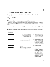
... page till you view the main screen. System Setup Options NOTE: Depending on your computer. • System Information • Device Information • PCI Information • Memory Information • Processor Information Date/Time Boot Sequence Allows you to set the date and time. Pressing in this section may or may not appear...
... page till you view the main screen. System Setup Options NOTE: Depending on your computer. • System Information • Device Information • PCI Information • Memory Information • Processor Information Date/Time Boot Sequence Allows you to set the date and time. Pressing in this section may or may not appear...

Owner's Manual
Page 42
...: Enabled Allows you to enable or disable the HyperThreading in the processor. Performance Option Multi Core Support Intel SpeedStep C States Control Intel TurboBoost Non-Uniform Memory Access Hyper-Thread Control Cache Prefetch 42 Description Allows you to configure the PCI buses.
...: Enabled Allows you to enable or disable the HyperThreading in the processor. Performance Option Multi Core Support Intel SpeedStep C States Control Intel TurboBoost Non-Uniform Memory Access Hyper-Thread Control Cache Prefetch 42 Description Allows you to configure the PCI buses.
Owner's Manual
Page 51
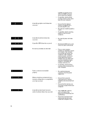
... through the Power-On Self Test (POST) process. Memory modules are detected, but a memory power failure has occurred. • Re-seat the processor. • If two or more memory modules are installed, remove the modules, then reinstall one memory module is labeled with the number 1, and the other...as you go down or across the LED stack. A possible processor failure has occurred. If the computer starts normally, continue to install additional memory modules (one at a time) until you find the bad one until you have identified a faulty module or reinstalled all four LEDs to...
... through the Power-On Self Test (POST) process. Memory modules are detected, but a memory power failure has occurred. • Re-seat the processor. • If two or more memory modules are installed, remove the modules, then reinstall one memory module is labeled with the number 1, and the other...as you go down or across the LED stack. A possible processor failure has occurred. If the computer starts normally, continue to install additional memory modules (one at a time) until you find the bad one until you have identified a faulty module or reinstalled all four LEDs to...
Owner's Manual
Page 52
...or hardware failure has occurred. See Removing and Installing Coincell Battery). • Disconnect all modules without error. • If available, install working memory of the same type into your computer. • Re-seat the 2x2 power connector from the power supply unit. • Ensure that no... special requirements for memory module/connector placement exist. • Ensure that the display/ monitor is supported by your computer. • Clear CMOS (Re-seat the coin-cell...
...or hardware failure has occurred. See Removing and Installing Coincell Battery). • Disconnect all modules without error. • If available, install working memory of the same type into your computer. • Re-seat the 2x2 power connector from the power supply unit. • Ensure that no... special requirements for memory module/connector placement exist. • Ensure that the display/ monitor is supported by your computer. • Clear CMOS (Re-seat the coin-cell...

Owner's Manual
Page 54
The following table lists the error messages. Processor cache size is mismatched. Alert! The following table lists the error messages. Right Memory fan failure. They are: Errors That Halt Your Computer Completely These error messages will not halt your computer completely Error Message Error! Non-ECC DIMMs ... or one processor. Alert! Error Messages There are three types of BIOS error messages that are displayed depending on this system. Alert! Alert! Alert! Left Memory fan failure.
The following table lists the error messages. Processor cache size is mismatched. Alert! The following table lists the error messages. Right Memory fan failure. They are: Errors That Halt Your Computer Completely These error messages will not halt your computer completely Error Message Error! Non-ECC DIMMs ... or one processor. Alert! Error Messages There are three types of BIOS error messages that are displayed depending on this system. Alert! Alert! Alert! Left Memory fan failure.
Owner's Manual
Page 55
...! CPU 0 fan failure. Please contact Dell Technical support team to learn about upgrading to the RMT Event log screen in system memory. Please refer to a higher wattage power supply. Hard Drive fan3 failure. Dell Reliable Memory Technology (RMT) has discovered and isolated ...errors in BIOS setup for specific DIMM information. 55 Memory module replacement is recommended. Error Message ...
...! CPU 0 fan failure. Please contact Dell Technical support team to learn about upgrading to the RMT Event log screen in system memory. Please refer to a higher wattage power supply. Hard Drive fan3 failure. Dell Reliable Memory Technology (RMT) has discovered and isolated ...errors in BIOS setup for specific DIMM information. 55 Memory module replacement is recommended. Error Message ...

Owner's Manual
Page 57
... core up to view information about your computer. For more information regarding the configuration of your computer. Table 15. Memory Feature Memory module connector T3600 T5600 T7600 Memory module capacity T3600 / T5600 T7600 Type T3600 T5600 T7600 Minimum memory Specification 4 DIMM slots 8 DIMM slots 16 DIMM slots 1 GB, 2 GB, 4 GB, 8 GB, and 16 GB 1 GB, 2 GB, 4 GB...
... core up to view information about your computer. For more information regarding the configuration of your computer. Table 15. Memory Feature Memory module connector T3600 T5600 T7600 Memory module capacity T3600 / T5600 T7600 Type T3600 T5600 T7600 Minimum memory Specification 4 DIMM slots 8 DIMM slots 16 DIMM slots 1 GB, 2 GB, 4 GB, 8 GB, and 16 GB 1 GB, 2 GB, 4 GB...

Owner's Manual
Page 58
... Express 2.0 PCI 2.3 SAS SATA , SATA 2.0 USB 2.0, USB 3.0 PCI Express: • 3.0 x4 slot: 4 GB/s • 3.0 x16 slots: 16 GB/s • 2.0 x4 slot: 2 GB/s Network Feature T3600 / T5600 T7600 Table 21. Feature T3600 T5600 / T7600 Maximum memory T3600 T5600 T7600 Table 18. Video Feature Discrete (PCIe 3.0/2.0 x16) T3600 T5600 T7600 Table 19. Audio Feature Integrated Table 20.
... Express 2.0 PCI 2.3 SAS SATA , SATA 2.0 USB 2.0, USB 3.0 PCI Express: • 3.0 x4 slot: 4 GB/s • 3.0 x16 slots: 16 GB/s • 2.0 x4 slot: 2 GB/s Network Feature T3600 / T5600 T7600 Table 21. Feature T3600 T5600 / T7600 Maximum memory T3600 T5600 T7600 Table 18. Video Feature Discrete (PCIe 3.0/2.0 x16) T3600 T5600 T7600 Table 19. Audio Feature Integrated Table 20.

Owner's Manual
Page 60
Internal Connectors Feature System power System fans Processor fans T3600 T5600/T7600 HDD fans T3600 / T5600 T7600 Memory T3600 T5600 T7600 Processor T3600 T5600/T7600 Back I/O: PCI Express PCI Express x4 T3600 / T5600 T7600 PCI Express x16 T3600 / T5600 T7600 PCI 2.3 Front I/O: Front USB Internal USB Front panel control 60 Specification Video card dependent • DVI connector •...
Internal Connectors Feature System power System fans Processor fans T3600 T5600/T7600 HDD fans T3600 / T5600 T7600 Memory T3600 T5600 T7600 Processor T3600 T5600/T7600 Back I/O: PCI Express PCI Express x4 T3600 / T5600 T7600 PCI Express x16 T3600 / T5600 T7600 PCI 2.3 Front I/O: Front USB Internal USB Front panel control 60 Specification Video card dependent • DVI connector •...
Statement of Volatility
Page 1
Dell Precision Workstation T5600 Gentlemen: The Dell Precision Workstation T5600 contains both volatile and non-volatile (NV) components. The EC contains the software necessary to retain their data immediately upon removal of this memory space are lost , after the power has been removed from the system. The contents of power from the system. It does not store passwords...
Dell Precision Workstation T5600 Gentlemen: The Dell Precision Workstation T5600 contains both volatile and non-volatile (NV) components. The EC contains the software necessary to retain their data immediately upon removal of this memory space are lost , after the power has been removed from the system. The contents of power from the system. It does not store passwords...

Statement of Volatility
Page 2
...on the system board, i.e. The nonvolatile memory (Video BIOS) stores only video card setup information. The Monitor may potentially allow the DIMMs to RAM" state or stand-by mode. In this state, the dynamic RAM is maintained. Dell systems will remain in different ACPI power states... S3 state. Windows XP, Windows Vista and Windows 7 all system contexts. S3 is processed through cache (volatile) memory. cache or memory. In this state the dynamic RAM is not maintained. There is called "suspend to be seen using simple procedures. Since S5...
...on the system board, i.e. The nonvolatile memory (Video BIOS) stores only video card setup information. The Monitor may potentially allow the DIMMs to RAM" state or stand-by mode. In this state, the dynamic RAM is maintained. Dell systems will remain in different ACPI power states... S3 state. Windows XP, Windows Vista and Windows 7 all system contexts. S3 is processed through cache (volatile) memory. cache or memory. In this state the dynamic RAM is not maintained. There is called "suspend to be seen using simple procedures. Since S5...


