Page 2
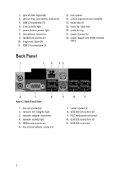
... 2.0 connectors (2) 9. PS/2 keyboard connector 10. USB 3.0 connector 2 3. drive activity light 7. USB 2.0 connectors (3) 12. network adapter connector 4. line-in/microphone connector 7. power button, power light 8. blank slot (1) 15. power supply unit (PSU) release latch Back Panel Figure 2. PS2/mouse connector 6. optical drive eject button (optional) 5. power connector 18. USB 2.0 connectors (3) 11. active...
... 2.0 connectors (2) 9. PS/2 keyboard connector 10. USB 3.0 connector 2 3. drive activity light 7. USB 2.0 connectors (3) 12. network adapter connector 4. line-in/microphone connector 7. power button, power light 8. blank slot (1) 15. power supply unit (PSU) release latch Back Panel Figure 2. PS2/mouse connector 6. optical drive eject button (optional) 5. power connector 18. USB 2.0 connectors (3) 11. active...
Page 3
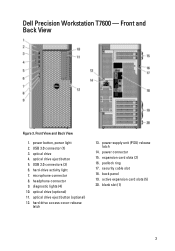
... (optional) 11. USB 2.0 connectors (3) 6. diagnostic lights (4) 10. power supply unit (PSU) release latch 14. security cable slot 18. Front and Back View Figure 3. hard-drive activity light 7. power connector 15. blank slot (1) 3 optical drive eject button 5. hard drive access cover-release latch 13. padlock ring 17. USB 3.0 connector (1) 3. Dell Precision Workstation T7600 - microphone connector 8.
... (optional) 11. USB 2.0 connectors (3) 6. diagnostic lights (4) 10. power supply unit (PSU) release latch 14. security cable slot 18. Front and Back View Figure 3. hard-drive activity light 7. power connector 15. blank slot (1) 3 optical drive eject button 5. hard drive access cover-release latch 13. padlock ring 17. USB 3.0 connector (1) 3. Dell Precision Workstation T7600 - microphone connector 8.
Page 4
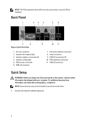
Back Panel View 1. line-in this section, read the safety information that shipped with your computer. For additional best practices information, see www.dell.com/regulatory_compliance NOTE: Some devices may not be included if you begin any of the procedures in /microphone connector 8. line-out connector 2. serial ...1. network adapter connectors (2) 4. PS/2 mouse connector 6. Back Panel Figure 4. USB 2.0 connector 7. USB 2.0 connectors (4) 10. Connect the network cable(s) (optional). 4 NOTE: The PCIe expansion slots (#15) are only active when a second CPU is installed.
Back Panel View 1. line-in this section, read the safety information that shipped with your computer. For additional best practices information, see www.dell.com/regulatory_compliance NOTE: Some devices may not be included if you begin any of the procedures in /microphone connector 8. line-out connector 2. serial ...1. network adapter connectors (2) 4. PS/2 mouse connector 6. Back Panel Figure 4. USB 2.0 connector 7. USB 2.0 connectors (4) 10. Connect the network cable(s) (optional). 4 NOTE: The PCIe expansion slots (#15) are only active when a second CPU is installed.
Owner's Manual
Page 12
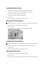
... to the back of the optical drive. 4. Install the cover. 3. Follow the procedures in After Working Inside Your Computer. Replace the thermal sensor in its slot and tighten the latch securing it from the hard drive. 12 Remove the cover. 3. Installing the Optical Drive 1. Connect the power cable to the computer...
... to the back of the optical drive. 4. Install the cover. 3. Follow the procedures in After Working Inside Your Computer. Replace the thermal sensor in its slot and tighten the latch securing it from the hard drive. 12 Remove the cover. 3. Installing the Optical Drive 1. Connect the power cable to the computer...

Owner's Manual
Page 19
... and attach the grommets. 2. Place the fan assembly in the computer and insert the latches. 7. Install the screws to secure the fan assembly to its slot in the chassis. 3. Place the air baffle in its connector. 10. Remove the cover. 3. Figure 2. Press down on the memory-securing clips on the memory...
... and attach the grommets. 2. Place the fan assembly in the computer and insert the latches. 7. Install the screws to secure the fan assembly to its slot in the chassis. 3. Place the air baffle in its connector. 10. Remove the cover. 3. Figure 2. Press down on the memory-securing clips on the memory...

Owner's Manual
Page 20
... Computer. Loosen the screws that secure the heat sink. 20 Figure 3. Press the coin-cell battery downward until the release latch springs back into the slot on the system board. 2. Follow the procedures in Before Working Inside Your Computer. 2. Place the coin-cell battery into place and secures it. 3. Install the...
... Computer. Loosen the screws that secure the heat sink. 20 Figure 3. Press the coin-cell battery downward until the release latch springs back into the slot on the system board. 2. Follow the procedures in Before Working Inside Your Computer. 2. Place the coin-cell battery into place and secures it. 3. Install the...

Owner's Manual
Page 22
.... Install: a) heat sink b) cover 6. 3. To remove the processor: NOTE: The processor cover is secured by two levers. To verify if your computer has dual processor slots, see the System Board Components. Place the processor in antistatic package. 4. Replace the processor cover. They have icons that indicate which lever closes first. Repeat...
.... Install: a) heat sink b) cover 6. 3. To remove the processor: NOTE: The processor cover is secured by two levers. To verify if your computer has dual processor slots, see the System Board Components. Place the processor in antistatic package. 4. Replace the processor cover. They have icons that indicate which lever closes first. Repeat...

Owner's Manual
Page 27
... system board. 6. Place the air baffle in the chassis. 3. Remove the cover. 3. Remove the system fans from its slot in the computer and insert the latches. 7. Place the fan assembly in its slot towards the front. 27 Install the screws to secure the fan assembly to their connectors on the system board...
... system board. 6. Place the air baffle in the chassis. 3. Remove the cover. 3. Remove the system fans from its slot in the computer and insert the latches. 7. Place the fan assembly in its slot towards the front. 27 Install the screws to secure the fan assembly to their connectors on the system board...

Owner's Manual
Page 28
Remove the baffle cover from the computer. 5. Remove the power cables. 6. 4. Remove the screws securing the PSU card to the slot. 28
Remove the baffle cover from the computer. 5. Remove the power cables. 6. 4. Remove the screws securing the PSU card to the slot. 28

Owner's Manual
Page 29
Follow the procedures in its slot. 3. Install the cover. 6. Tighten the screws to secure the PSU card in After Working Inside Your Computer. Removing the Front Bezel 1. Follow the procedures in their slots. 4. Installing the PSU Card 1. Gently pry the front bezel retention clips away from the computer. Replace the power cables in Before Working Inside Your Computer. 2. Remove the PSU card from the chassis located at the edge of front bezel. 29 Replace the baffle cover in its slot. 5. 7. Replace the PSU card in its slot. 2. Remove the cover. 3.
Follow the procedures in its slot. 3. Install the cover. 6. Tighten the screws to secure the PSU card in After Working Inside Your Computer. Removing the Front Bezel 1. Follow the procedures in their slots. 4. Installing the PSU Card 1. Gently pry the front bezel retention clips away from the computer. Replace the power cables in Before Working Inside Your Computer. 2. Remove the PSU card from the chassis located at the edge of front bezel. 29 Replace the baffle cover in its slot. 5. 7. Replace the PSU card in its slot. 2. Remove the cover. 3.

Owner's Manual
Page 30
... release the hooks on the chassis front. 2. Rotate the bezel towards the computer to engage the front-bezel retention clips until they click into the slots on the opposite edge of the front panel into place. 3. 4. Remove: a) cover b) front bezel 3. Removing the Front Input/Output (I /O panel. 30...
... release the hooks on the chassis front. 2. Rotate the bezel towards the computer to engage the front-bezel retention clips until they click into the slots on the opposite edge of the front panel into place. 3. 4. Remove: a) cover b) front bezel 3. Removing the Front Input/Output (I /O panel. 30...

Owner's Manual
Page 32
... cables to the I /O) Panel 1. Disconnect the speaker cable from the chassis. Install: a) front bezel b) cover 7. Remove the cover. 3. Figure 4. 6. Slide the USB 3.0 module in its slot. 5. Tighten the screws securing the USB 3.0 module to the front I /O panel to the chassis. 7. Tighten the screws securing the front I /O panel. 6. Removing the Speaker 1. Replace...
... cables to the I /O) Panel 1. Disconnect the speaker cable from the chassis. Install: a) front bezel b) cover 7. Remove the cover. 3. Figure 4. 6. Slide the USB 3.0 module in its slot. 5. Tighten the screws securing the USB 3.0 module to the front I /O panel to the chassis. 7. Tighten the screws securing the front I /O panel. 6. Removing the Speaker 1. Replace...

Owner's Manual
Page 36
... internal speaker connector 25. RTCRST jumper 28. 24-pin power connector 29. PCI slot 2. DIMM slots 9. front panel audio connector 15. PSWD jumper 23. HDD & optical drive connectors 27. PCIe x1 slot 5. HDD1 fan connector 16. coin-cell battery 17. system fan 3 connector 22...connector 36 internal USB 2.0 connector 30. PCIe x16 slot (wired as x4) 3. CPU fan socket 11. system fan 1 connector 18. HDD temperature sensor connector 20. remote power enable 19. 1. PCIe x16 slot (accelerated graphics port) 6. DIMM slots 13. front panel & USB 2.0 connector 24. ...
... internal speaker connector 25. RTCRST jumper 28. 24-pin power connector 29. PCI slot 2. DIMM slots 9. front panel audio connector 15. PSWD jumper 23. HDD & optical drive connectors 27. PCIe x1 slot 5. HDD1 fan connector 16. coin-cell battery 17. system fan 3 connector 22...connector 36 internal USB 2.0 connector 30. PCIe x16 slot (wired as x4) 3. CPU fan socket 11. system fan 1 connector 18. HDD temperature sensor connector 20. remote power enable 19. 1. PCIe x16 slot (accelerated graphics port) 6. DIMM slots 13. front panel & USB 2.0 connector 24. ...
Owner's Manual
Page 51
... boots, add the peripheral cards back one by one until you have identified a faulty module or reinstalled all peripheral cards from the PCI and PCI-E slots and reboot the computer.
... boots, add the peripheral cards back one by one until you have identified a faulty module or reinstalled all peripheral cards from the PCI and PCI-E slots and reboot the computer.
Owner's Manual
Page 54
... 13. - Hard Drive fan1 failure. Alert! Hard Drive fan2 failure. Correctable memory error has been detected in system memory. Please contact Dell Technical support team to learn about upgrading to enter the system setup. The following table lists the error messages. Table 12. Cover was ...to the RMT Event log screen in BIOS setup for a few seconds, and then continue to boot. Dell Reliable Memory Technology (RMT) has discovered and isolated errors in memory slot DIMMx. Your current power supply does not support the recent configuration changes made to work. Alert! Hard ...
... 13. - Hard Drive fan1 failure. Alert! Hard Drive fan2 failure. Correctable memory error has been detected in system memory. Please contact Dell Technical support team to learn about upgrading to enter the system setup. The following table lists the error messages. Table 12. Cover was ...to the RMT Event log screen in BIOS setup for a few seconds, and then continue to boot. Dell Reliable Memory Technology (RMT) has discovered and isolated errors in memory slot DIMMx. Your current power supply does not support the recent configuration changes made to work. Alert! Hard ...
Owner's Manual
Page 57
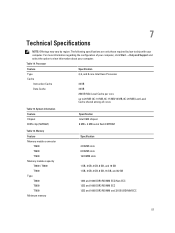
...: Offerings may vary by law to ship with your computer. Table 14. Memory Feature Memory module connector T3600 T5600 T7600 Memory module capacity T3600 / T5600 T7600 Type T3600 T5600 T7600 Minimum memory Specification 4 DIMM slots 8 DIMM slots 16 DIMM slots 1 GB, 2 GB, 4 GB, 8 GB, and 16 GB 1 GB, 2 GB, 4 GB, 8 GB, 16 GB, and 32 GB...
...: Offerings may vary by law to ship with your computer. Table 14. Memory Feature Memory module connector T3600 T5600 T7600 Memory module capacity T3600 / T5600 T7600 Type T3600 T5600 T7600 Minimum memory Specification 4 DIMM slots 8 DIMM slots 16 DIMM slots 1 GB, 2 GB, 4 GB, 8 GB, and 16 GB 1 GB, 2 GB, 4 GB, 8 GB, 16 GB, and 32 GB...
Owner's Manual
Page 58
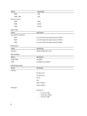
Video Feature Discrete (PCIe 3.0/2.0 x16) T3600 T5600 T7600 Table 18. Expansion Bus Feature Bus Type: Bus Speed: 58 Specification 2 GB 4 GB 64 GB 128 GB 512 GB Specification up to 2 full-... Intel 82759 Intel 82759 and Intel 82754 Specification PCI Express 3.0 PCI Express 2.0 PCI 2.3 SAS SATA , SATA 2.0 USB 2.0, USB 3.0 PCI Express: • 3.0 x4 slot: 4 GB/s • 3.0 x16 slots: 16 GB/s • 2.0 x4 slot: 2 GB/s Feature T3600 T5600 / T7600 Maximum memory T3600 T5600 T7600 Table 17. Network Feature T3600 / T5600 T7600 Table 20. Audio Feature Integrated Table 19.
Video Feature Discrete (PCIe 3.0/2.0 x16) T3600 T5600 T7600 Table 18. Expansion Bus Feature Bus Type: Bus Speed: 58 Specification 2 GB 4 GB 64 GB 128 GB 512 GB Specification up to 2 full-... Intel 82759 Intel 82759 and Intel 82754 Specification PCI Express 3.0 PCI Express 2.0 PCI 2.3 SAS SATA , SATA 2.0 USB 2.0, USB 3.0 PCI Express: • 3.0 x4 slot: 4 GB/s • 3.0 x16 slots: 16 GB/s • 2.0 x4 slot: 2 GB/s Feature T3600 T5600 / T7600 Maximum memory T3600 T5600 T7600 Table 17. Network Feature T3600 / T5600 T7600 Table 20. Audio Feature Integrated Table 19.


