Owner's Manual
Page 3
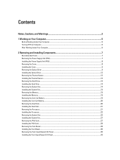
......12 Removing the Hard Drive...12 Installing the Hard Drive ...14 Removing the System Fan...14 Installing the System Fan...19 Removing the Memory...19 Installing the Memory...19 Removing the Coin-Cell Battery...19 Installing the Coin-Cell Battery...20 Removing the Heat Sink...20 Installing the Heat Sink...21 Removing...
......12 Removing the Hard Drive...12 Installing the Hard Drive ...14 Removing the System Fan...14 Installing the System Fan...19 Removing the Memory...19 Installing the Memory...19 Removing the Coin-Cell Battery...19 Installing the Coin-Cell Battery...20 Removing the Heat Sink...20 Installing the Heat Sink...21 Removing...
Owner's Manual
Page 4
Removing the Speaker...32 Installing the Speaker...33 Removing the System Board...33 Installing the System Board...35 System Board Components...35 3 Additional Information...37 Memory Module Guidelines...37 Power Supply Unit (PSU) Lock...37 4 System Setup...39 Boot Sequence...39 Navigation Keys...39 System Setup Options...40 Updating the BIOS ...... Diagnostic LEDs...51 Error Messages...54 Errors That Do Not Halt Your Computer...54 Errors That Soft Halt Your Computer...54 7 Technical Specifications...57 8 Contacting Dell...65
Removing the Speaker...32 Installing the Speaker...33 Removing the System Board...33 Installing the System Board...35 System Board Components...35 3 Additional Information...37 Memory Module Guidelines...37 Power Supply Unit (PSU) Lock...37 4 System Setup...39 Boot Sequence...39 Navigation Keys...39 System Setup Options...40 Updating the BIOS ...... Diagnostic LEDs...51 Error Messages...54 Errors That Do Not Halt Your Computer...54 Errors That Soft Halt Your Computer...54 7 Technical Specifications...57 8 Contacting Dell...65

Owner's Manual
Page 19
...the fans in place. 3. Route and connect the system board cable to its slot in After Working Inside Your Computer. Installing the Memory 1. Press down on the memory-securing clips on the system board. 5. Remove the cover. 19 Place the air baffle in its connector. 10. Install: a) ...optical drive b) hard drive c) PCI card d) intrusion switch e) cover 11. Insert the memory module into the memory socket. 2. Follow the procedures in the computer and insert the latches. 7. Follow the procedures in the chassis. 3. Place the fan assembly in...
...the fans in place. 3. Route and connect the system board cable to its slot in After Working Inside Your Computer. Installing the Memory 1. Press down on the memory-securing clips on the system board. 5. Remove the cover. 19 Place the air baffle in its connector. 10. Install: a) ...optical drive b) hard drive c) PCI card d) intrusion switch e) cover 11. Insert the memory module into the memory socket. 2. Follow the procedures in the computer and insert the latches. 7. Follow the procedures in the chassis. 3. Place the fan assembly in...

Owner's Manual
Page 34
j) front input/output (I/O) panel k) speakers l) heat sink m) heat-sink fan n) memory module(s) o) processor 3. Remove the screws that secure the system board to the chassis. 5. Lift the system board in an upward direction and remove it from the system board. 4. Disconnect all the cables from the computer. 34
j) front input/output (I/O) panel k) speakers l) heat sink m) heat-sink fan n) memory module(s) o) processor 3. Remove the screws that secure the system board to the chassis. 5. Lift the system board in an upward direction and remove it from the system board. 4. Disconnect all the cables from the computer. 34

Owner's Manual
Page 35
Install: a) processor b) memory module(s) c) heat-sink fan d) heat sink e) speakers f) front input/output (I/O) panel g) PCI card h) PSU card i) system fan j) hard drive k) thermal sensor l) coin-cell battery m) optical ...
Install: a) processor b) memory module(s) c) heat-sink fan d) heat sink e) speakers f) front input/output (I/O) panel g) PCI card h) PSU card i) system fan j) hard drive k) thermal sensor l) coin-cell battery m) optical ...
Owner's Manual
Page 37
... dual-rank modules, the quad-rank modules must be installed beginning with different speeds are installed, they operate at the speed of the slowest installed memory module(s). To secure the PSU, remove the screw from the chassis. For example, A1, A2 or 1,2,3. • If the quad-rank... memory modules are part of your computer may be labelled differently depending on removing the cover, see Removing the cover. For information on the hardware configuration. ...
... dual-rank modules, the quad-rank modules must be installed beginning with different speeds are installed, they operate at the speed of the slowest installed memory module(s). To secure the PSU, remove the screw from the chassis. For example, A1, A2 or 1,2,3. • If the quad-rank... memory modules are part of your computer may be labelled differently depending on removing the cover, see Removing the cover. For information on the hardware configuration. ...

Owner's Manual
Page 40
... appear. Moves to the next focus area. System Setup Options NOTE: Depending on your computer. • System Information • Device Information • PCI Information • Memory Information • Processor Information Date/Time Boot Sequence Allows you to set the date and time. Moves to the previous page till you view the...
... appear. Moves to the next focus area. System Setup Options NOTE: Depending on your computer. • System Information • Device Information • PCI Information • Memory Information • Processor Information Date/Time Boot Sequence Allows you to set the date and time. Moves to the previous page till you view the...
Owner's Manual
Page 51
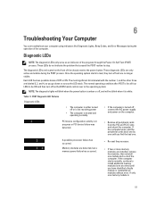
...the other three are labeled 2, 3, and 4, as you go down or across the LED stack. Memory modules are detected, but a memory power failure has occurred. • Re-seat the processor. • If two or more memory modules are located on the computer. Table 11. A possible processor failure has occurred. The normal operating... off and are only active and visible during the operation of OFF or ON. If the computer starts normally, continue to install additional memory modules (one memory module is for all peripheral cards from the PCI and PCI-E slots and reboot the computer.
...the other three are labeled 2, 3, and 4, as you go down or across the LED stack. Memory modules are detected, but a memory power failure has occurred. • Re-seat the processor. • If two or more memory modules are located on the computer. Table 11. A possible processor failure has occurred. The normal operating... off and are only active and visible during the operation of OFF or ON. If the computer starts normally, continue to install additional memory modules (one memory module is for all peripheral cards from the PCI and PCI-E slots and reboot the computer.
Owner's Manual
Page 52
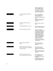
...restart the computer. See Removing and Installing Coincell Battery). • Disconnect all cable connections. • If two or more memory modules are using is plugged into a discrete graphic card. • Re-seat any installed graphics cards. • If available, install a working...8226; Re-seat the 2x2 power connector from the power supply unit. • Ensure that no special requirements for memory module/connector placement exist. • Ensure that the memory you are installed, remove the modules, then reinstall one module and restart the computer. A possible system board resource...
...restart the computer. See Removing and Installing Coincell Battery). • Disconnect all cable connections. • If two or more memory modules are using is plugged into a discrete graphic card. • Re-seat any installed graphics cards. • If available, install a working...8226; Re-seat the 2x2 power connector from the power supply unit. • Ensure that no special requirements for memory module/connector placement exist. • Ensure that the memory you are installed, remove the modules, then reinstall one module and restart the computer. A possible system board resource...
Owner's Manual
Page 54
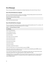
... a soft halt of the issue. Table 13. - Left Memory fan failure. Alert! Please contact Dell Technical support team to learn about upgrading to work. Alert! Alert! Dell Reliable Memory Technology (RMT) has discovered and isolated errors in memory slot DIMMx. Correctable memory error has been detected in system memory. Error Messages There are two types of BIOS...
... a soft halt of the issue. Table 13. - Left Memory fan failure. Alert! Please contact Dell Technical support team to learn about upgrading to work. Alert! Alert! Dell Reliable Memory Technology (RMT) has discovered and isolated errors in memory slot DIMMx. Correctable memory error has been detected in system memory. Error Messages There are two types of BIOS...
Owner's Manual
Page 55
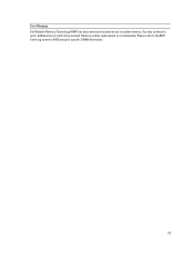
Additional errors will not be isolated. Please refer to work. Memory module replacement is recommended. Error Message Dell Reliable Memory Technology (RMT) has discovered and isolated errors in BIOS setup for specific DIMM information. 55 You may continue to the RMT Event log screen in system memory.
Additional errors will not be isolated. Please refer to work. Memory module replacement is recommended. Error Message Dell Reliable Memory Technology (RMT) has discovered and isolated errors in BIOS setup for specific DIMM information. 55 You may continue to the RMT Event log screen in system memory.
Owner's Manual
Page 57
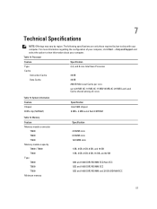
... KB Data Cache 32 KB 256 KB Mid-Level Cache per core up to view information about your computer. Memory Feature Memory module connector T3600 T5600 T7600 Memory module capacity T3600 / T5600 T7600 Type T3600 T5600 T7600 Minimum memory Specification 4 DIMM slots 8 DIMM slots 16 DIMM slots 1 GB, 2 GB, 4 GB, 8 GB, and 16 GB 1 GB, 2 GB, 4 GB...
... KB Data Cache 32 KB 256 KB Mid-Level Cache per core up to view information about your computer. Memory Feature Memory module connector T3600 T5600 T7600 Memory module capacity T3600 / T5600 T7600 Type T3600 T5600 T7600 Minimum memory Specification 4 DIMM slots 8 DIMM slots 16 DIMM slots 1 GB, 2 GB, 4 GB, 8 GB, and 16 GB 1 GB, 2 GB, 4 GB...
Owner's Manual
Page 58
... T7600 Table 20. Video Feature Discrete (PCIe 3.0/2.0 x16) T3600 T5600 T7600 Table 18. Expansion Bus Feature Bus Type: Bus Speed: 58 Specification 2 GB 4 GB 64 GB 128 GB 512 GB Specification up to 2 full-... Express 3.0 PCI Express 2.0 PCI 2.3 SAS SATA , SATA 2.0 USB 2.0, USB 3.0 PCI Express: • 3.0 x4 slot: 4 GB/s • 3.0 x16 slots: 16 GB/s • 2.0 x4 slot: 2 GB/s Feature T3600 T5600 / T7600 Maximum memory T3600 T5600 T7600 Table 17. Audio Feature Integrated Table 19.
... T7600 Table 20. Video Feature Discrete (PCIe 3.0/2.0 x16) T3600 T5600 T7600 Table 18. Expansion Bus Feature Bus Type: Bus Speed: 58 Specification 2 GB 4 GB 64 GB 128 GB 512 GB Specification up to 2 full-... Express 3.0 PCI Express 2.0 PCI 2.3 SAS SATA , SATA 2.0 USB 2.0, USB 3.0 PCI Express: • 3.0 x4 slot: 4 GB/s • 3.0 x16 slots: 16 GB/s • 2.0 x4 slot: 2 GB/s Feature T3600 T5600 / T7600 Maximum memory T3600 T5600 T7600 Table 17. Audio Feature Integrated Table 19.
Owner's Manual
Page 60
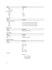
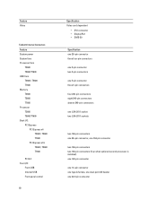
Internal Connectors Feature System power System fans Processor fans T3600 T5600/T7600 HDD fans T3600 / T5600 T7600 Memory T3600 T5600 T7600 Processor T3600 T5600/T7600 Back I/O: PCI Express PCI Express x4 T3600 / T5600 T7600 PCI Express x16 T3600 / T5600 T7600 PCI 2.3 Front I/O: Front USB Internal USB Front panel control 60 Specification Video card dependent • DVI connector •...
Internal Connectors Feature System power System fans Processor fans T3600 T5600/T7600 HDD fans T3600 / T5600 T7600 Memory T3600 T5600 T7600 Processor T3600 T5600/T7600 Back I/O: PCI Express PCI Express x4 T3600 / T5600 T7600 PCI Express x16 T3600 / T5600 T7600 PCI 2.3 Front I/O: Front USB Internal USB Front panel control 60 Specification Video card dependent • DVI connector •...
Statement of Volatility
Page 1
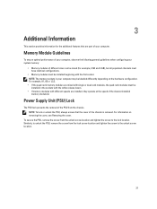
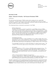
... power has been removed from the system. This memory contains custom configuration data required by the BIOS to be managed by the TPM device for example, cold No information pertaining to a state where it is removed from the component. Dell Inc. Dell Precision Workstation T3600 Gentlemen: The Dell Precision Workstation T3600 contains both volatile and non-volatile (NV...
... power has been removed from the system. This memory contains custom configuration data required by the BIOS to be managed by the TPM device for example, cold No information pertaining to a state where it is removed from the component. Dell Inc. Dell Precision Workstation T3600 Gentlemen: The Dell Precision Workstation T3600 contains both volatile and non-volatile (NV...
Statement of Volatility
Page 2
..., does not contain any user data, and is read/write by mode. Windows XP, Windows Vista and Windows 7 all registers. The nonvolatile memory (Video BIOS) stores only video card setup information. Any associated internal NVRAM is factory programmed, does not contain any user data, and is called...power. There is not maintained. These devices may potentially allow the DIMMs to be able to go to be seen using simple procedures. Dell systems will destroy system data in the system supports S3 state. There are input/output devices, whereas the DVD-ROM is coming out ...
..., does not contain any user data, and is read/write by mode. Windows XP, Windows Vista and Windows 7 all registers. The nonvolatile memory (Video BIOS) stores only video card setup information. Any associated internal NVRAM is factory programmed, does not contain any user data, and is called...power. There is not maintained. These devices may potentially allow the DIMMs to be able to go to be seen using simple procedures. Dell systems will destroy system data in the system supports S3 state. There are input/output devices, whereas the DVD-ROM is coming out ...


