
Owner's manual
Page 3
... Intrusion Switch...8 Removing the Front Panel...9 Installing the Front Panel...10 Removing the Expansion Card...10 Installing the Expansion Card...11 Memory Module Guidelines...11 Removing the Memory...11 Installing the Memory...11 Removing the Coin-Cell Battery...12 Installing the Coin-Cell Battery...12 Removing the Hard Drive...12 Installing the Hard...
... Intrusion Switch...8 Removing the Front Panel...9 Installing the Front Panel...10 Removing the Expansion Card...10 Installing the Expansion Card...11 Memory Module Guidelines...11 Removing the Memory...11 Installing the Memory...11 Removing the Coin-Cell Battery...12 Installing the Coin-Cell Battery...12 Removing the Hard Drive...12 Installing the Hard...

Owner's manual
Page 11
...installed beginning with single or dual-rank modules, the quad-rank modules must be labelled differently depending on each side of the memory module, and lift the memory module out of different sizes can be mixed (for example, 2 GB and 4 GB), but all populated channels must have...first. 2. Push the card retention clip inward, until the retention-clips spring back to secure the card. 3. Install the cover. 4. Memory Module Guidelines To ensure optimal performance of your computer, observe the following general guidelines when configuring your computer may be installed in After Working ...
...installed beginning with single or dual-rank modules, the quad-rank modules must be labelled differently depending on each side of the memory module, and lift the memory module out of different sizes can be mixed (for example, 2 GB and 4 GB), but all populated channels must have...first. 2. Push the card retention clip inward, until the retention-clips spring back to secure the card. 3. Install the cover. 4. Memory Module Guidelines To ensure optimal performance of your computer, observe the following general guidelines when configuring your computer may be installed in After Working ...

Owner's manual
Page 32
... reset jumper (RTCRST) 32 System Board Components The following image displays the system board components. PCI Express x16 (wired as x4) connector 2. PCI Card connector 3. Memory Module Connectors (DIMM_1-4) 12. Front USB 16. Password Jumper (PSWD) 21. Coin-Cell Battery socket 5. SATA Drive Connectors 15. Power Switch Connector (PWR_SW) 13. Internal...
... reset jumper (RTCRST) 32 System Board Components The following image displays the system board components. PCI Express x16 (wired as x4) connector 2. PCI Card connector 3. Memory Module Connectors (DIMM_1-4) 12. Front USB 16. Password Jumper (PSWD) 21. Coin-Cell Battery socket 5. SATA Drive Connectors 15. Power Switch Connector (PWR_SW) 13. Internal...

Owner's manual
Page 34
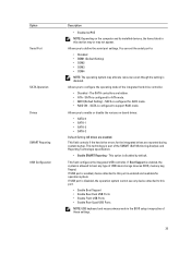
.... General Option System Information Description This section lists the primary hardware features of your computer. • System Information • Device Information • PCI Information • Memory Information • Processor Information Boot Sequence Allows you to find an operating system. NOTE: For the standard graphics browser only. Pressing in the main screen...
.... General Option System Information Description This section lists the primary hardware features of your computer. • System Information • Device Information • PCI Information • Memory Information • Processor Information Boot Sequence Allows you to find an operating system. NOTE: For the standard graphics browser only. Pressing in the main screen...
Owner's manual
Page 35
The SATA controllers are hidden. • ATA - This technology is part of USB mass storage devices (HDD, memory key, floppy). If Boot Support is enabled, the system is enabled and available for the integrated drives are reported during system startup. This field controls ...
The SATA controllers are hidden. • ATA - This technology is part of USB mass storage devices (HDD, memory key, floppy). If Boot Support is enabled, the system is enabled and available for the integrated drives are reported during system startup. This field controls ...

Owner's manual
Page 37
... - Allows you to enable or disable the option to the system and hard disk passwords are not affected if you access the Option Read Only Memory (OROM) configuration screens via the hotkeys during boot. This option is set to disabled. • Disable - Description Specifies whether the process will revert to Enable...
... - Allows you to enable or disable the option to the system and hard disk passwords are not affected if you access the Option Read Only Memory (OROM) configuration screens via the hotkeys during boot. This option is set to disabled. • Disable - Description Specifies whether the process will revert to Enable...
Owner's manual
Page 45
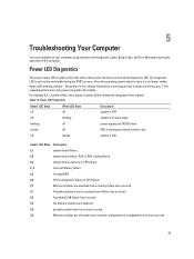
... board failure, PSU or PSU cabling failure 2,3 system board, memory or CPU failure 2, 4 Coin-cell battery failure 2,5 Corrupt BIOS 2,6 CPU configuration failure or CPU failure 2,7 Memory modules are detected, but a memory failure has occurred 3,1 Possible peripheral card or system board failure... has occurred 3,2 A possible USB failure has occurred 3,3 No memory modules are detected 3,4 possible system board error has occurred 3,5 Memory modules are detected, but a memory configuration or compatibility error has occurred 45 Power LED Diagnostics Amber LED ...
... board failure, PSU or PSU cabling failure 2,3 system board, memory or CPU failure 2, 4 Coin-cell battery failure 2,5 Corrupt BIOS 2,6 CPU configuration failure or CPU failure 2,7 Memory modules are detected, but a memory failure has occurred 3,1 Possible peripheral card or system board failure... has occurred 3,2 A possible USB failure has occurred 3,3 No memory modules are detected 3,4 possible system board error has occurred 3,5 Memory modules are detected, but a memory configuration or compatibility error has occurred 45 Power LED Diagnostics Amber LED ...

Owner's manual
Page 46
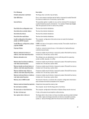
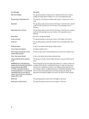
... utility. Diskette drive 0 seek failure A cable may be faulty or improperly seated. Previous attempts at checkpoint the same error. Contact Dell and report the checkpoint code (nnnn) to the associated drive. Alert! Data error The floppy or hard drive cannot read failure The... (ECC) on , try a different disk. 46 Controller has failed The hard drive or the associated controller is removed. Code Cause 1-3-2 Memory failure Error Messages Error Message Description Address mark not found The BIOS found a faulty disk sector or could not find a particular disk sector....
... utility. Diskette drive 0 seek failure A cable may be faulty or improperly seated. Previous attempts at checkpoint the same error. Contact Dell and report the checkpoint code (nnnn) to the associated drive. Alert! Data error The floppy or hard drive cannot read failure The... (ECC) on , try a different disk. 46 Controller has failed The hard drive or the associated controller is removed. Code Cause 1-3-2 Memory failure Error Messages Error Message Description Address mark not found The BIOS found a faulty disk sector or could not find a particular disk sector....
Owner's manual
Page 47
...amount of paper. Non-system disk or disk error The floppy disk in System Setup may be faulty or improperly seated. Reinstall the memory modules and, if necessary, replace them . Keyboard failure A cable or connector may be loose, or the keyboard or keyboard/mouse ...controller may be incorrect. Reinstall the memory modules and, if necessary, replace them . Reinstall the memory modules and, if necessary, replace them . Either replace the floppy disk with the operating system, another program, or ...
...amount of paper. Non-system disk or disk error The floppy disk in System Setup may be faulty or improperly seated. Reinstall the memory modules and, if necessary, replace them . Keyboard failure A cable or connector may be loose, or the keyboard or keyboard/mouse ...controller may be incorrect. Reinstall the memory modules and, if necessary, replace them . Reinstall the memory modules and, if necessary, replace them . Either replace the floppy disk with the operating system, another program, or ...
Owner's manual
Page 48
...re-set -please run the System Setup program The time or date stored in protected mode The keyboard controller may be malfunctioning or a memory module may be loose. replace your hard drive by calling your computer type). Write fault The operating system cannot write to the floppy...that does not have a bootable operating system installed on the disk, or the requested sector is operating outside of your support desk or Dell. Requested sector not found The operating system cannot locate a sector on the system board may be malfunctioning. Sector not found The operating system...
...re-set -please run the System Setup program The time or date stored in protected mode The keyboard controller may be malfunctioning or a memory module may be loose. replace your hard drive by calling your computer type). Write fault The operating system cannot write to the floppy...that does not have a bootable operating system installed on the disk, or the requested sector is operating outside of your support desk or Dell. Requested sector not found The operating system cannot locate a sector on the system board may be malfunctioning. Sector not found The operating system...
Owner's manual
Page 49
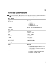
... Speed Connectors Capacity Minimum Memory Maximum memory Specification DDR3 NECC and ECC 1333MHz / 1600 MHz four DIMM slots 2 GB , 4 GB, 8 GB 2 GB NECC, 4 GB ECC 16 GB NECC, 32 GB ECC Table ...
... Speed Connectors Capacity Minimum Memory Maximum memory Specification DDR3 NECC and ECC 1333MHz / 1600 MHz four DIMM slots 2 GB , 4 GB, 8 GB 2 GB NECC, 4 GB ECC 16 GB NECC, 32 GB ECC Table ...

Owner's manual
Page 52
...: Link integrity light on integrated network adapter Network activity light on state; Feature PCI Express x16 data width (maximum) - 16 PCI Express lanes Serial ATA Memory Internal USB System Fan Front panel control Thermal Sensor Processor Processor Fan Service mode jumper Password clear jumper RTC reset jumper Internal speaker Intruder connector...
...: Link integrity light on integrated network adapter Network activity light on state; Feature PCI Express x16 data width (maximum) - 16 PCI Express lanes Serial ATA Memory Internal USB System Fan Front panel control Thermal Sensor Processor Processor Fan Service mode jumper Password clear jumper RTC reset jumper Internal speaker Intruder connector...


