
Setup Guide
Page 2
.... HDMI connector 6. cooling vent 7. power connector 8. microphone connector 11. power light 15. optical-drive eject hole 19. battery status light 14. track stick buttons (3) 22. memory card slot 16. volume control buttons Figure 2. eSATA/USB 2.0 connector 5. optical drive 20. caps lock LED 24. Back View 1. device status lights 25. USB 3.0 connectors...
.... HDMI connector 6. cooling vent 7. power connector 8. microphone connector 11. power light 15. optical-drive eject hole 19. battery status light 14. track stick buttons (3) 22. memory card slot 16. volume control buttons Figure 2. eSATA/USB 2.0 connector 5. optical drive 20. caps lock LED 24. Back View 1. device status lights 25. USB 3.0 connectors...
Setup Guide
Page 4
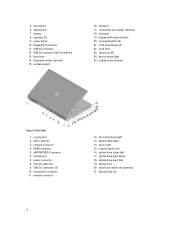
.... caps lock LED 24. optical-drive eject hole 19. track stick buttons (3) 22. device status lights 25. power connector 8. power light 15. optical drive 20. memory reader slot 16. display 8. USB 3.0 connector 12. security cable slot 9. hard-drive status light 13. VGA connector 3. touchpad 19. touchpad buttons (3) 21. 5. cooling vent 7. keyboard...
.... caps lock LED 24. optical-drive eject hole 19. track stick buttons (3) 22. device status lights 25. power connector 8. power light 15. optical drive 20. memory reader slot 16. display 8. USB 3.0 connector 12. security cable slot 9. hard-drive status light 13. VGA connector 3. touchpad 19. touchpad buttons (3) 21. 5. cooling vent 7. keyboard...

Setup Guide
Page 6
...law to turn on the support site at least once before you turn on system memory size, operating system, and other external device, such as a mouse or keyboard (optional). Figure 9. Specifications NOTE: Offerings may be downloaded from dell.com/support. NOTE: A 64-bit operating system is recommended that you install any... about the configuration of your computer go to Help and Support in your Owner's Manual available on and shut down your computer at dell.com/support. Power AC Adapter M4800 M6800 Output Input voltage 180 W 240 W 19.5 V 100 VAC - 240 VAC 6
...law to turn on the support site at least once before you turn on system memory size, operating system, and other external device, such as a mouse or keyboard (optional). Figure 9. Specifications NOTE: Offerings may be downloaded from dell.com/support. NOTE: A 64-bit operating system is recommended that you install any... about the configuration of your computer go to Help and Support in your Owner's Manual available on and shut down your computer at dell.com/support. Power AC Adapter M4800 M6800 Output Input voltage 180 W 240 W 19.5 V 100 VAC - 240 VAC 6

Owners Manual
Page 3
... Keyboard...16 Installing the Keyboard...18 Removing the Base Cover...19 Installing the Base Cover...21 Removing the Primary Memory...21 Installing the Primary Memory...21 Removing the Secondary Memory...21 Installing the Secondary Memory...22 Removing the Optical Drive...22 Installing the Optical Drive...23 Removing the Hard Drive...24 Installing the Hard...
... Keyboard...16 Installing the Keyboard...18 Removing the Base Cover...19 Installing the Base Cover...21 Removing the Primary Memory...21 Installing the Primary Memory...21 Removing the Secondary Memory...21 Installing the Secondary Memory...22 Removing the Optical Drive...22 Installing the Optical Drive...23 Removing the Hard Drive...24 Installing the Hard...
Owners Manual
Page 11
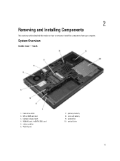
Micro SIM card slot 3. video-card fan 6. WLAN card 7. primary memory 8. WWAN card / mSATA SSD card 5. optical drive 11 system fan 10. back 1. 2 Removing and Installing Components This section provides detailed information on how to remove or install the components from your computer. System Overview Inside view - coin-cell battery 9. hard-drive latch 2. battery release latch 4.
Micro SIM card slot 3. video-card fan 6. WLAN card 7. primary memory 8. WWAN card / mSATA SSD card 5. optical drive 11 system fan 10. back 1. 2 Removing and Installing Components This section provides detailed information on how to remove or install the components from your computer. System Overview Inside view - coin-cell battery 9. hard-drive latch 2. battery release latch 4.

Owners Manual
Page 12
processor heatsink 5. wi-fi switch board Removing the Secure Digital (SD) Card 1. Press in the SD card into place. 2. Push in on the SD card to release it clicks into its slot until it from the computer. I/O Board 4. Unified Security Hub (USH) Board 7. secondary memory 8. Slide the SD card out of the computer. video card 3. front 1. Installing the SD Card 1. video-card heatsink 2. Inside view - Follow the procedures in After Working Inside Your Computer. 12 express card module 6. Follow the procedures in Before Working Inside Your Computer. 2.
processor heatsink 5. wi-fi switch board Removing the Secure Digital (SD) Card 1. Press in the SD card into place. 2. Push in on the SD card to release it clicks into its slot until it from the computer. I/O Board 4. Unified Security Hub (USH) Board 7. secondary memory 8. Slide the SD card out of the computer. video card 3. front 1. Installing the SD Card 1. video-card heatsink 2. Inside view - Follow the procedures in After Working Inside Your Computer. 12 express card module 6. Follow the procedures in Before Working Inside Your Computer. 2.

Owners Manual
Page 21
... Inside Your Computer. Pry the retention clips away from the memory module until it pops up the memory module and remove it from the computer. 21 Install the battery. 4. Insert the memory into the memory socket. 2. Tighten the screws to secure the base cover ... Computer. 2. Install the: a) base cover b) battery 4. Remove the: a) battery b) keyboard trim c) keyboard NOTE: The secondary memory is located below the keyboard. 3. Installing the Primary Memory 1. Lift up . Installing the Base Cover 1. Slide in and place the base cover to the computer. 3. Removing the Secondary...
... Inside Your Computer. Pry the retention clips away from the memory module until it pops up the memory module and remove it from the computer. 21 Install the battery. 4. Insert the memory into the memory socket. 2. Tighten the screws to secure the base cover ... Computer. 2. Install the: a) base cover b) battery 4. Remove the: a) battery b) keyboard trim c) keyboard NOTE: The secondary memory is located below the keyboard. 3. Installing the Primary Memory 1. Lift up . Installing the Base Cover 1. Slide in and place the base cover to the computer. 3. Removing the Secondary...

Owners Manual
Page 22
Installing the Secondary Memory 1. Remove the screw that secures the optical drive to remove it from the computer. 22 Follow the procedures in Before Working Inside Your Computer. 2. Removing the Optical Drive 1. Follow the procedures in After Working Inside Your Computer. Pry and slide out the optical drive to the computer. 4. Press down the memory to secure the memory module to the system board. 3. Install the: a) keyboard b) keyboard trim c) battery 4. Remove the: a) battery b) base cover 3. Insert the secondary memory into the memory socket. 2.
Installing the Secondary Memory 1. Remove the screw that secures the optical drive to remove it from the computer. 22 Follow the procedures in Before Working Inside Your Computer. 2. Removing the Optical Drive 1. Follow the procedures in After Working Inside Your Computer. Pry and slide out the optical drive to the computer. 4. Press down the memory to secure the memory module to the system board. 3. Install the: a) keyboard b) keyboard trim c) battery 4. Remove the: a) battery b) base cover 3. Insert the secondary memory into the memory socket. 2.

Owners Manual
Page 46
h) battery 4. Follow the procedures in Before Working Inside Your Computer. 2. Follow the procedures in After Working Inside Your Computer. Disconnect the coin-cell battery cable. 4. Disconnect the USH connector cable and wi-fi switch cable. 46 Removing the System Board 1. Remove the: a) SD card b) ExpressCard c) battery d) base cover e) keyboard trim f) keyboard g) optical drive h) hard drive i) primary memory j) secondary memory k) processor fan l) video-card fan m) palmrest n) heat sink o) processor p) video-card heat sink q) video card r) I/O board s) display assembly 3.
h) battery 4. Follow the procedures in Before Working Inside Your Computer. 2. Follow the procedures in After Working Inside Your Computer. Disconnect the coin-cell battery cable. 4. Disconnect the USH connector cable and wi-fi switch cable. 46 Removing the System Board 1. Remove the: a) SD card b) ExpressCard c) battery d) base cover e) keyboard trim f) keyboard g) optical drive h) hard drive i) primary memory j) secondary memory k) processor fan l) video-card fan m) palmrest n) heat sink o) processor p) video-card heat sink q) video card r) I/O board s) display assembly 3.

Owners Manual
Page 48
Connect the power connector cable to the computer. 4. Install the: a) display assembly b) I/O board c) video card d) video-card heat sink e) processor f) heat sink g) palmrest h) video-card fan i) processor fan j) secondary memory k) primary memory l) hard drive 48 Installing the System Board 1. Connect the following cables: a) USH connector b) wi-fi switch cable c) wireless board connectors d) coin-cell battery 5. Tighten the screws to secure the system board to the system board. 2. Install the wireless cards (if available). 6. Place the system board in its compartment. 3.
Connect the power connector cable to the computer. 4. Install the: a) display assembly b) I/O board c) video card d) video-card heat sink e) processor f) heat sink g) palmrest h) video-card fan i) processor fan j) secondary memory k) primary memory l) hard drive 48 Installing the System Board 1. Connect the following cables: a) USH connector b) wi-fi switch cable c) wireless board connectors d) coin-cell battery 5. Tighten the screws to secure the system board to the system board. 2. Install the wireless cards (if available). 6. Place the system board in its compartment. 3.

Owners Manual
Page 49
Remove the: a) SD card b) ExpressCard c) battery d) base cover e) keyboard trim f) keyboard g) optical drive h) hard drive i) primary memory j) secondary memory k) processor fan l) video-card fan m) palm rest n) processor heatsink o) processor p) video-card heatsink q) video card r) I/O board s) display assembly t) system board 3. Follow the procedures in After ...
Remove the: a) SD card b) ExpressCard c) battery d) base cover e) keyboard trim f) keyboard g) optical drive h) hard drive i) primary memory j) secondary memory k) processor fan l) video-card fan m) palm rest n) processor heatsink o) processor p) video-card heatsink q) video card r) I/O board s) display assembly t) system board 3. Follow the procedures in After ...

Owners Manual
Page 50
.... 3. Install the: a) system board b) display assembly c) I/O board d) video card e) video-card heat sink f) processor g) processor heatsink h) palm rest i) video-card fan j) processor fan k) secondary memory l) primary memory m) hard drive n) optical drive o) keyboard p) keyboard trim q) base cover r) battery s) ExpressCard t) SD card 3. Follow the procedures in its slot and route the power-connector cable...
.... 3. Install the: a) system board b) display assembly c) I/O board d) video card e) video-card heat sink f) processor g) processor heatsink h) palm rest i) video-card fan j) processor fan k) secondary memory l) primary memory m) hard drive n) optical drive o) keyboard p) keyboard trim q) base cover r) battery s) ExpressCard t) SD card 3. Follow the procedures in its slot and route the power-connector cable...

Owners Manual
Page 58
... can also choose the Boot List option. This option is enabled. 58 Table 2. System Setup Options NOTE: Depending on your computer. • System Information • Memory Information • Processor Information • Device Information Battery Information Boot Sequence Displays the charge status of your computer and its installed devices, the items listed...
... can also choose the Boot List option. This option is enabled. 58 Table 2. System Setup Options NOTE: Depending on your computer. • System Information • Memory Information • Processor Information • Device Information Battery Information Boot Sequence Displays the charge status of your computer and its installed devices, the items listed...
Owners Manual
Page 73
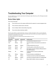
...failed in a power management mode. Blinking Blinking Solid A possible graphics card/video failure has occurred. Solid Blinking Solid The memory modules are installed/detected. Blinking Blinking Off System failed on the top or left side of the computer. Blinking Solid ...indicate battery charge status. Blinking Off Blinking The USB controller encountered a problem during initialization. Off Blinking Off Memory failed to initialize or memory is preventing the system from that they can troubleshoot your computer using indicators like Diagnostic Lights, Beep Codes,...
...failed in a power management mode. Blinking Blinking Solid A possible graphics card/video failure has occurred. Solid Blinking Solid The memory modules are installed/detected. Blinking Blinking Off System failed on the top or left side of the computer. Blinking Solid ...indicate battery charge status. Blinking Off Blinking The USB controller encountered a problem during initialization. Off Blinking Off Memory failed to initialize or memory is preventing the system from that they can troubleshoot your computer using indicators like Diagnostic Lights, Beep Codes,...


