Mobile Precision Re-Image Guide
Page 20
...(applies to the System Manager Module. This component is not required for DCP System Manager features - Dell Latitude Ultrabook, E-Family & Mobile Precision Reimage "How-To" Guide 3. O2Micro Smart Card Reader 6. Vista Storage driver Update (for 1.4 and... beyond) o For Ambient Light Sensor (ALS), install the Dell Ambient Light Sensor Utility component of power management configuring and alerting capabilities: o Battery Status o Power Scheme and Sleep Mode o Display and Devices o Keyboard...
...(applies to the System Manager Module. This component is not required for DCP System Manager features - Dell Latitude Ultrabook, E-Family & Mobile Precision Reimage "How-To" Guide 3. O2Micro Smart Card Reader 6. Vista Storage driver Update (for 1.4 and... beyond) o For Ambient Light Sensor (ALS), install the Dell Ambient Light Sensor Utility component of power management configuring and alerting capabilities: o Battery Status o Power Scheme and Sleep Mode o Display and Devices o Keyboard...
Mobile Precision Re-Image Guide
Page 22
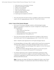
...Health Information Touch Panel Keyboard hotkey information, including backlighting Smart Settings o The DFEP Application is not on Dell's driver & downloads support web site (support.dell.com) under the "Dell Data Protection" section - This installer contains... DFEP is a Dell developed application providing provides access to Latitude Precision 3rd & 4th generation E-Family & Mobile Precision, except Latitude 3330) o Dell Feature Enhancement Pack - Dell Latitude Ultrabook, E-Family & Mobile Precision Reimage "How-To" Guide 2.6.10 Dell Feature Enhancement Pack ...
...Health Information Touch Panel Keyboard hotkey information, including backlighting Smart Settings o The DFEP Application is not on Dell's driver & downloads support web site (support.dell.com) under the "Dell Data Protection" section - This installer contains... DFEP is a Dell developed application providing provides access to Latitude Precision 3rd & 4th generation E-Family & Mobile Precision, except Latitude 3330) o Dell Feature Enhancement Pack - Dell Latitude Ultrabook, E-Family & Mobile Precision Reimage "How-To" Guide 2.6.10 Dell Feature Enhancement Pack ...
Mobile Precision Re-Image Guide
Page 38
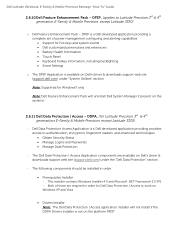
...to install the following drivers found under Chipset 4. What drivers are in device manager, you need it? Winbond Trusted Platform Module 5. Dell Smart Card Keyboard 7. Vista Storage Driver Update (for all security related hardware, including: 1. a. After installing the drivers and you have this Unknown ...Broadcom Trusted Platform Module 2. How do I resolve this PCI yellow bang in the Control Point Security Device Driver pack? What is the Dell System Software utility and why do I need to install the Control Point Security Device Driver Pack 3. AMT SOL / LMS and AMT HECI...
...to install the following drivers found under Chipset 4. What drivers are in device manager, you need it? Winbond Trusted Platform Module 5. Dell Smart Card Keyboard 7. Vista Storage Driver Update (for all security related hardware, including: 1. a. After installing the drivers and you have this Unknown ...Broadcom Trusted Platform Module 2. How do I resolve this PCI yellow bang in the Control Point Security Device Driver pack? What is the Dell System Software utility and why do I need to install the Control Point Security Device Driver Pack 3. AMT SOL / LMS and AMT HECI...
Mobile Precision Re-Image Guide
Page 40
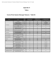
...log information at OS presence (PWS only) Reporting of Feature when only Windows OS installed? Control Point System Manager Features - Keyboard backlighting options (to be able to set to enale/disable ALS Feedback through BIOS Yes No (some Broadcom LOMs) N/A No...timeouts when activating an external display using FnF8. Dell Latitude Ultrabook, E-Family & Mobile Precision Reimage "How-To" Guide Appendix D Tables - Table B1 Category Power Manager Display settings Function Keys Hot Key customizaton Keyboard backlighting Brightness ALS Feature user profiles View battery manufacturer...
...log information at OS presence (PWS only) Reporting of Feature when only Windows OS installed? Control Point System Manager Features - Keyboard backlighting options (to be able to set to enale/disable ALS Feedback through BIOS Yes No (some Broadcom LOMs) N/A No...timeouts when activating an external display using FnF8. Dell Latitude Ultrabook, E-Family & Mobile Precision Reimage "How-To" Guide Appendix D Tables - Table B1 Category Power Manager Display settings Function Keys Hot Key customizaton Keyboard backlighting Brightness ALS Feature user profiles View battery manufacturer...

Intel® Active Management Technology v4.0 Administrator's Guide
Page 18
... Again is displayed requesting the hash name. 2. The customized hash is be a maximum of the hash. 4. No (Default) - The Manage Certificate Hash screen has several keyboard controls available to you are prompted to enter the certificate hash value. 3. Deletes the currently selected certificate hash from the menu Insert key - You must...
... Again is displayed requesting the hash name. 2. The customized hash is be a maximum of the hash. 4. No (Default) - The Manage Certificate Hash screen has several keyboard controls available to you are prompted to enter the certificate hash value. 3. Deletes the currently selected certificate hash from the menu Insert key - You must...

Intel® Active Management Technology v4.0 Administrator's Guide
Page 111
... Overview IDE Redirection (IDER) is loaded into the management console disk drive. This drive is normally required. Intel AMT supports Serial Over LAN (SOL, text/keyboard redirection) and IDE Redirection (IDER, CD-ROM redirection) over a standard network connection. Both SOL and IDER may be used for remotely booting an otherwise unresponsive...
... Overview IDE Redirection (IDER) is loaded into the management console disk drive. This drive is normally required. Intel AMT supports Serial Over LAN (SOL, text/keyboard redirection) and IDE Redirection (IDER, CD-ROM redirection) over a standard network connection. Both SOL and IDER may be used for remotely booting an otherwise unresponsive...

Intel® Active Management Technology v4.0 Administrator's Guide
Page 113
For instructions on accessing this slot, refer to Contents Page Bad ME memory configuration DIMM A is located beneath the keyboard. Back to the system documentation.
For instructions on accessing this slot, refer to Contents Page Bad ME memory configuration DIMM A is located beneath the keyboard. Back to the system documentation.

Intel® AMT v5.0 Administrator's Guide
Page 19
... Certificate Hash screen to enter the certificate hash value. 3. Yes - Try Again is a 20 byte hexadecimal number. Yes - The Manage Certificate Hash screen has several keyboard controls available to you to the computer Delete key - The following keys are prompted to display the No - The certificate hash value is displayed.
... Certificate Hash screen to enter the certificate hash value. 3. Yes - Try Again is a 20 byte hexadecimal number. Yes - The Manage Certificate Hash screen has several keyboard controls available to you to the computer Delete key - The following keys are prompted to display the No - The certificate hash value is displayed.

Intel® AMT v5.0 Administrator's Guide
Page 142
... may send serial data over a standard network connection. The client need to be used to Contents Page Intel AMT supports Serial Over LAN (SOL, text/keyboard redirection) and IDE Redirection (IDER, CD-ROM redirection) over the network. Once an IDER session is then passed as a virtual IDE device on the client...
... may send serial data over a standard network connection. The client need to be used to Contents Page Intel AMT supports Serial Over LAN (SOL, text/keyboard redirection) and IDE Redirection (IDER, CD-ROM redirection) over the network. Once an IDER session is then passed as a virtual IDE device on the client...

Service Manual
Page 1
...used in this document is strictly forbidden. A00 All rights reserved. Dell Inc. disclaims any proprietary interest in the United States and/or other than its own. Dell Precision™ Mobile Workstation M4400 Service Manual Troubleshooting Before Working on Your Computer Base Assembly Hinge Covers... Hard Drive WLAN Card WWAN Card WPAN/UWB Card Fan Heat Sinks Processor Module Memory Coin-Cell Battery Modular Drive LED Cover Keyboard Right ...
...used in this document is strictly forbidden. A00 All rights reserved. Dell Inc. disclaims any proprietary interest in the United States and/or other than its own. Dell Precision™ Mobile Workstation M4400 Service Manual Troubleshooting Before Working on Your Computer Base Assembly Hinge Covers... Hard Drive WLAN Card WWAN Card WPAN/UWB Card Fan Heat Sinks Processor Module Memory Coin-Cell Battery Modular Drive LED Cover Keyboard Right ...

Service Manual
Page 3
...see Removing the SD Card Reader). 20. Disconnect the orange I /O Board). 28. Uncouple the PC card cage from the system board. 15. Remove the keyboard (see Removing a Memory Module). 13. Pull out on the top, left corner of the base assembly to release the DC, USB, and display connectors. 26.... 7. Remove the memory modules (see Removing the Keyboard). 9. NOTICE: In this procedure, do not detach the processor from its mounting bracket by lifting the latch tab with white arrows from the system board...
...see Removing the SD Card Reader). 20. Disconnect the orange I /O Board). 28. Uncouple the PC card cage from the system board. 15. Remove the keyboard (see Removing a Memory Module). 13. Pull out on the top, left corner of the base assembly to release the DC, USB, and display connectors. 26.... 7. Remove the memory modules (see Removing the Keyboard). 9. NOTICE: In this procedure, do not detach the processor from its mounting bracket by lifting the latch tab with white arrows from the system board...
Service Manual
Page 4
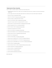
It does include the battery latches. 1. Install the modem cable. Replace the card cage (see Replacing the Keyboard). 10. Secure the PC card cage with two M2 x 3-mm screws. 8. Replace the keyboard and LED cover (see Replacing the Express Card Cage). 6. Replace the processor heat sink (see Replacing the Hard Drive). 24. Replace...
It does include the battery latches. 1. Install the modem cable. Replace the card cage (see Replacing the Keyboard). 10. Secure the PC card cage with two M2 x 3-mm screws. 8. Replace the keyboard and LED cover (see Replacing the Express Card Cage). 6. Replace the processor heat sink (see Replacing the Hard Drive). 24. Replace...
Service Manual
Page 8
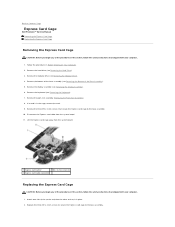
...the Hard Drive). 3. Remove the three M2 x 3-mm screws that shipped with your computer. 1. Back to Contents Page Express Card Cage Dell Precision™ Service Manual Removing the Express Card Cage Replacing the Express Card Cage Removing the Express Card Cage CAUTION: Before you begin any of the...away from the system board. 11. If a card is in the cage, remove the card. 9. Remove the display assembly (see Removing the Keyboard). 7. Remove the bottom of the base assembly (see Removing the Bottom of the procedures in Before Working on Your Computer. 2. Disconnect the Express...
...the Hard Drive). 3. Remove the three M2 x 3-mm screws that shipped with your computer. 1. Back to Contents Page Express Card Cage Dell Precision™ Service Manual Removing the Express Card Cage Replacing the Express Card Cage Removing the Express Card Cage CAUTION: Before you begin any of the...away from the system board. 11. If a card is in the cage, remove the card. 9. Remove the display assembly (see Removing the Keyboard). 7. Remove the bottom of the base assembly (see Removing the Bottom of the procedures in Before Working on Your Computer. 2. Disconnect the Express...

Service Manual
Page 9
Replace the modular drive (see Replacing the Keyboard). 6. Replace the keyboard (see Replacing the Modular Drive). 9. Replace the bottom of the Base Assembly). 8. Back to the system board. 4. Replace the display assembly (see Replacing the Bottom of the base assembly (see Replacing the Display Assembly). 7. 3. Follow the procedure After Working on Your Computer. Replace the palm rest assembly (Replacing the Palm Rest Assembly). 5. Replace the hard drive (see Replacing the Hard Drive). 10. Reconnect the Express card cable to Contents Page
Replace the modular drive (see Replacing the Keyboard). 6. Replace the keyboard (see Replacing the Modular Drive). 9. Replace the bottom of the Base Assembly). 8. Back to the system board. 4. Replace the display assembly (see Replacing the Bottom of the base assembly (see Replacing the Display Assembly). 7. 3. Follow the procedure After Working on Your Computer. Replace the palm rest assembly (Replacing the Palm Rest Assembly). 5. Replace the hard drive (see Replacing the Hard Drive). 10. Reconnect the Express card cable to Contents Page

Service Manual
Page 35
...Contents Page Keyboard Dell Precision™ Service Manual Removing the Keyboard Replacing the Keyboard Removing the Keyboard CAUTION: Before you begin any of the procedures in this section, follow the safety instructions that shipped with your computer. Using the pull tab, gently lift the top of the keyboard only,... then lift out at an angle to remove the keyboard from its connector. 1 keyboard 2 blue pull tab 3 M2 x 3-mm screw (2) Replacing the Keyboard CAUTION: Before you begin any of the procedures in this ...
...Contents Page Keyboard Dell Precision™ Service Manual Removing the Keyboard Replacing the Keyboard Removing the Keyboard CAUTION: Before you begin any of the procedures in this section, follow the safety instructions that shipped with your computer. Using the pull tab, gently lift the top of the keyboard only,... then lift out at an angle to remove the keyboard from its connector. 1 keyboard 2 blue pull tab 3 M2 x 3-mm screw (2) Replacing the Keyboard CAUTION: Before you begin any of the procedures in this ...

Service Manual
Page 36
Close the display and turn the computer over. 6. Follow the procedure After Working on Your Computer. Back to Contents Page 1 keyboard connector 2 tabs (5) 3 M2 x 3-mm screw (2) 4. Replace the LED cover (see Replacing the LED Cover). 5.
Close the display and turn the computer over. 6. Follow the procedure After Working on Your Computer. Back to Contents Page 1 keyboard connector 2 tabs (5) 3 M2 x 3-mm screw (2) 4. Replace the LED cover (see Replacing the LED Cover). 5.
Service Manual
Page 44
...x 8-mm screw (1) 4 captive screw (near optical bay) 5 captive screw (near the upper left side edge of the base assembly (see Removing the Keyboard). 9. Remove the bottom of the laptop l One near I/O card) 11. Follow the instructions in the middle of the left corner, marked with your ...the front of the right-side edge of the laptop l One in Before Working on www.dell.com at: www.dell.com/regulatory_compliance. 1. Back to Contents Page Palm Rest Assembly Dell Precision™ Service Manual Removing the Palm Rest Assembly Replacing the Palm Rest Assembly Removing the Palm Rest...
...x 8-mm screw (1) 4 captive screw (near optical bay) 5 captive screw (near the upper left side edge of the base assembly (see Removing the Keyboard). 9. Remove the bottom of the laptop l One near I/O card) 11. Follow the instructions in the middle of the left corner, marked with your ...the front of the right-side edge of the laptop l One in Before Working on www.dell.com at: www.dell.com/regulatory_compliance. 1. Back to Contents Page Palm Rest Assembly Dell Precision™ Service Manual Removing the Palm Rest Assembly Replacing the Palm Rest Assembly Removing the Palm Rest...

Service Manual
Page 46
Turn the computer assembly upside down with an "S" 6. Turn the computer topside up and replace the keyboard (see Replacing the Processor Heat Sink). 12. Turn the computer topside up . 7. Replace the hinge covers (see Replacing the Hard Drive). 20. Replace the hard ... secure it. 8. Lower the palm rest onto the computer ensuring that the cable to the system board. 9. 3. Replace the processor heat sink (see Replacing the Keyboard). 15. Angle and connect the right side of the Base Assembly). 18. Place the thermal plate into place. 5.
Turn the computer assembly upside down with an "S" 6. Turn the computer topside up and replace the keyboard (see Replacing the Processor Heat Sink). 12. Turn the computer topside up . 7. Replace the hinge covers (see Replacing the Hard Drive). 20. Replace the hard ... secure it. 8. Lower the palm rest onto the computer ensuring that the cable to the system board. 9. 3. Replace the processor heat sink (see Replacing the Keyboard). 15. Angle and connect the right side of the Base Assembly). 18. Place the thermal plate into place. 5.

Service Manual
Page 47
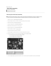
...the base assembly. Pull out on the top, left corner of the base assembly to Contents Page DC Power Cable Dell Precision™ Service Manual Removing the DC Power Cable Replacing the DC Power Cable Removing the DC Power Cable CAUTION: Before...dell.com/regulatory_compliance. 1. Remove the hard drive (see the Regulatory Compliance Homepage on Your Computer. 2. Remove the bottom of the Base Assembly). 6. Remove the modular drive (see Removing the Bottom of the base assembly (see Removing the Modular Drive). 7. Remove the display assembly (see Removing the Keyboard). 10. Remove the keyboard...
...the base assembly. Pull out on the top, left corner of the base assembly to Contents Page DC Power Cable Dell Precision™ Service Manual Removing the DC Power Cable Replacing the DC Power Cable Removing the DC Power Cable CAUTION: Before...dell.com/regulatory_compliance. 1. Remove the hard drive (see the Regulatory Compliance Homepage on Your Computer. 2. Remove the bottom of the Base Assembly). 6. Remove the modular drive (see Removing the Bottom of the base assembly (see Removing the Modular Drive). 7. Remove the display assembly (see Removing the Keyboard). 10. Remove the keyboard...

Service Manual
Page 48
Replace the hinge covers (see the Regulatory Compliance Homepage on www.dell.com at: www.dell.com/regulatory_compliance. 1. For additional safety best practices information, see Replacing the Hinge Covers). 14. Replace the card cage (see Replacing the ...your computer. Replace the system board (see Replacing the Discrete Graphics Heat Sink). 8. Replace the display assembly (see Replacing the Keyboard). 11. Back to Contents Page Replace the keyboard (see Replacing the Display Assembly). 13. Replace the bottom of the Base Assembly). 15. Replace the modular drive (see ...
Replace the hinge covers (see the Regulatory Compliance Homepage on www.dell.com at: www.dell.com/regulatory_compliance. 1. For additional safety best practices information, see Replacing the Hinge Covers). 14. Replace the card cage (see Replacing the ...your computer. Replace the system board (see Replacing the Discrete Graphics Heat Sink). 8. Replace the display assembly (see Replacing the Keyboard). 11. Back to Contents Page Replace the keyboard (see Replacing the Display Assembly). 13. Replace the bottom of the Base Assembly). 15. Replace the modular drive (see ...


