
Quick Reference Guide
Page 8
... recommended that you have ordered. 3 Connect the AC adapter to the AC adapter connector on the computer and to the electrical outlet. 4 Open the computer display and press the power button to turn on page 9). Setting Up Your Computer CAUTION: Before you begin any of the procedures in this section, follow...
... recommended that you have ordered. 3 Connect the AC adapter to the AC adapter connector on the computer and to the electrical outlet. 4 Open the computer display and press the power button to turn on page 9). Setting Up Your Computer CAUTION: Before you begin any of the procedures in this section, follow...

Quick Reference Guide
Page 9
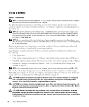
About Your Computer Front View 1 2 3 15 4 14 5 13 12 6 11 7 10 1 display latch 4 omni-directional microphone 7 keyboard 10 touch pad/track stick buttons 13 volume control buttons 9 8 2 display 5 device status lights 8 touch pad 11 track stick 14 mute button 3 power button 6 speakers (2) 9 fingerprint reader (optional) 12 keyboard status lights 15 ambient light sensor Quick Reference Guide 9
About Your Computer Front View 1 2 3 15 4 14 5 13 12 6 11 7 10 1 display latch 4 omni-directional microphone 7 keyboard 10 touch pad/track stick buttons 13 volume control buttons 9 8 2 display 5 device status lights 8 touch pad 11 track stick 14 mute button 3 power button 6 speakers (2) 9 fingerprint reader (optional) 12 keyboard status lights 15 ambient light sensor Quick Reference Guide 9
Quick Reference Guide
Page 12
...Using optical drives • Using wireless communications devices, PC Cards, ExpressCards, media memory cards, or USB devices • Using high-brightness display settings, 3D screen savers, or other computers with a compatible battery purchased from children. You can hold a charge) decreases over time. CAUTION... Information Guide. See "Battery Disposal" in the battery bay. Using a Battery Battery Performance NOTE: For information about the Dell warranty for advice on operating conditions. To view battery charge status, access the Control Panel→ Power Options, and then...
...Using optical drives • Using wireless communications devices, PC Cards, ExpressCards, media memory cards, or USB devices • Using high-brightness display settings, 3D screen savers, or other computers with a compatible battery purchased from children. You can hold a charge) decreases over time. CAUTION... Information Guide. See "Battery Disposal" in the battery bay. Using a Battery Battery Performance NOTE: For information about the Dell warranty for advice on operating conditions. To view battery charge status, access the Control Panel→ Power Options, and then...

Quick Reference Guide
Page 13
... the status button on the taskbar. The Battery Meter displays status, battery health, charge level, and charge completion time for the battery in the Microsoft® Windows® taskbar, and click Help. For more information about QuickSet, right-click the QuickSet icon in Dell QuickSet. To check the Power Meter, double-click...
... the status button on the taskbar. The Battery Meter displays status, battery health, charge level, and charge completion time for the battery in the Microsoft® Windows® taskbar, and click Help. For more information about QuickSet, right-click the QuickSet icon in Dell QuickSet. To check the Power Meter, double-click...
Quick Reference Guide
Page 14
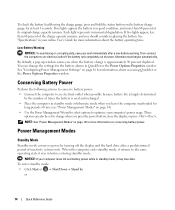
... outlet when possible because battery life is largely determined by the number of the charge capacity remains, and you press the power button, close the display, or press . NOTE: See "Power Management Modes" on page 14). • Use the Power Management Wizard to select options to an electrical outlet. To check... conserving battery power. Each light represents incremental degradation. To enter standby mode: • Click Start or → Shut Down→ Stand by turning off the display and the hard drive after a low-battery warning.
... outlet when possible because battery life is largely determined by the number of the charge capacity remains, and you press the power button, close the display, or press . NOTE: See "Power Management Modes" on page 14). • Use the Power Management Wizard to select options to an electrical outlet. To check... conserving battery power. Each light represents incremental degradation. To enter standby mode: • Click Start or → Shut Down→ Stand by turning off the display and the hard drive after a low-battery warning.

Quick Reference Guide
Page 15
... Press . The computer may not operate correctly after the computer exits hibernate mode. To exit standby mode, press the power button or open the display depending on hibernate mode, see "Installing a PC Card or Express Card" in your online User's Guide), or simply restart (reboot) your computer... Wizard, use one of the following methods to enter hibernate mode: - Close the display. - NOTE: Some PC Cards or ExpressCards may take a short time to exit hibernate mode. Close the display. - Hibernate Mode Hibernate mode conserves power by copying system data to the same operating...
... Press . The computer may not operate correctly after the computer exits hibernate mode. To exit standby mode, press the power button or open the display depending on hibernate mode, see "Installing a PC Card or Express Card" in your online User's Guide), or simply restart (reboot) your computer... Wizard, use one of the following methods to enter hibernate mode: - Close the display. - NOTE: Some PC Cards or ExpressCards may take a short time to exit hibernate mode. Close the display. - Hibernate Mode Hibernate mode conserves power by copying system data to the same operating...

Quick Reference Guide
Page 19
...• If necessary, uninstall and then reinstall the program. R U N T H E D E L L D I A G N O S T I C S - When to Use the Dell Diagnostics If you experience a problem with the operating system installed on your computer. • Ensure that your computer meets the minimum hardware requirements needed to... test displays in the Product Information Guide. NOTICE: The Dell Diagnostics works only on page 19. Enter the system setup program, review your computer's configuration information...
...• If necessary, uninstall and then reinstall the program. R U N T H E D E L L D I A G N O S T I C S - When to Use the Dell Diagnostics If you experience a problem with the operating system installed on your computer. • Ensure that your computer meets the minimum hardware requirements needed to... test displays in the Product Information Guide. NOTICE: The Dell Diagnostics works only on page 19. Enter the system setup program, review your computer's configuration information...

Quick Reference Guide
Page 20
...press immediately. NOTE: If you wait too long and the operating system logo appears, continue to wait until you see "Contacting Dell" in your system board, keyboard, display, memory, hard drive, etc. • During the assessment, answer any key to start -up, the computer boots according ... system logo appears, continue to wait until you see "Contacting Dell" in one time only. NOTE: If the computer is known to a docking device (docked), undock it. NOTE: If your computer cannot display a screen image, contact Dell (see the Microsoft® Windows® desktop; then, shut...
...press immediately. NOTE: If you wait too long and the operating system logo appears, continue to wait until you see "Contacting Dell" in your system board, keyboard, display, memory, hard drive, etc. • During the assessment, answer any key to start -up, the computer boots according ... system logo appears, continue to wait until you see "Contacting Dell" in one time only. NOTE: If the computer is known to a docking device (docked), undock it. NOTE: If your computer cannot display a screen image, contact Dell (see the Microsoft® Windows® desktop; then, shut...

Quick Reference Guide
Page 22
...complete, close the Main Menu screen. 6 Remove the Dell Drivers and Utilities media (if applicable). 22 Quick Reference Guide The Dell Diagnostics obtains configuration information for more information. Describes the test and may not display the names of all the components installed on your computer...of the test and any error conditions encountered. The device list may indicate requirements for the selected device. Displays your computer. To exit the Dell Diagnostics and restart the computer, close the test screen to return to your hardware configuration for running the...
...complete, close the Main Menu screen. 6 Remove the Dell Drivers and Utilities media (if applicable). 22 Quick Reference Guide The Dell Diagnostics obtains configuration information for more information. Describes the test and may not display the names of all the components installed on your computer...of the test and any error conditions encountered. The device list may indicate requirements for the selected device. Displays your computer. To exit the Dell Diagnostics and restart the computer, close the test screen to return to your hardware configuration for running the...

Service Manual (English Only)
Page 1
..., Inc. All rights reserved. is a registered trademark owned by Dell under license. Model PP04X June 2007 Rev. Reproduction in trademarks and trade names other than its own. Dell™ Precision™ M4300 Service Manual Before You Begin Internal Card with Bluetooth® Wireless ...Technology Hard Drive Memory FCM (Flash Cache Module) Coin-Cell Battery Hinge Cover Keyboard Communications Cards Using Cards PC Card Reader Display Assembly Palm Rest ...
..., Inc. All rights reserved. is a registered trademark owned by Dell under license. Model PP04X June 2007 Rev. Reproduction in trademarks and trade names other than its own. Dell™ Precision™ M4300 Service Manual Before You Begin Internal Card with Bluetooth® Wireless ...Technology Hard Drive Memory FCM (Flash Cache Module) Coin-Cell Battery Hinge Cover Keyboard Communications Cards Using Cards PC Card Reader Display Assembly Palm Rest ...

Service Manual (English Only)
Page 2
... periodically touching a connector on the back panel of the computer. 1. Remove the display assembly (see Palm Rest). 8. Back to Contents Page Base Dell™ Precision™ M4300 Service Manual CAUTION: Before performing the following procedures, follow the safety instructions in Before... You Begin. 2. Remove the palm rest (see Removing the Display Assembly). 7. Remove the processor thermal-cooling...
... periodically touching a connector on the back panel of the computer. 1. Remove the display assembly (see Palm Rest). 8. Back to Contents Page Base Dell™ Precision™ M4300 Service Manual CAUTION: Before performing the following procedures, follow the safety instructions in Before... You Begin. 2. Remove the palm rest (see Removing the Display Assembly). 7. Remove the processor thermal-cooling...

Service Manual (English Only)
Page 3
Back to Contents Page Battery Latch Dell™ Precision™ M4300 Service Manual CAUTION: Before performing the following procedures, follow the safety instructions in Before You Begin. 2. Remove the display assembly (see Removing the System Board). 9. Remove the system board (see Removing the Display Assembly). 6. Remove the keyboard (see Processor Thermal-Cooling Assembly). 8. Remove the processor...
Back to Contents Page Battery Latch Dell™ Precision™ M4300 Service Manual CAUTION: Before performing the following procedures, follow the safety instructions in Before You Begin. 2. Remove the display assembly (see Removing the System Board). 9. Remove the system board (see Removing the Display Assembly). 6. Remove the keyboard (see Processor Thermal-Cooling Assembly). 8. Remove the processor...

Service Manual (English Only)
Page 11
... cam screw to prevent intermittent contact between the cam screw and processor. Remove the display assembly (see Display Assembly). 5. Seating the processor module properly in Before You Begin. 2. Be careful not to Contents Page Processor Module Dell™ Precision™ M4300 Service Manual Removing the Processor Module Installing the Processor Module Removing the Processor Module...
... cam screw to prevent intermittent contact between the cam screw and processor. Remove the display assembly (see Display Assembly). 5. Seating the processor module properly in Before You Begin. 2. Be careful not to Contents Page Processor Module Dell™ Precision™ M4300 Service Manual Removing the Processor Module Installing the Processor Module Removing the Processor Module...

Service Manual (English Only)
Page 13
...assembly. 1 processor thermal-cooling assembly 7. Back to Contents Page Processor Thermal-Cooling Assembly Dell™ Precision™ M4300 Service Manual CAUTION: Before performing the following procedures, follow the safety instructions in the... Product Information Guide. Remove the hinge cover (see Palm Rest). 6. Loosen in Before You Begin. 2. Remove the keyboard (see Display Assembly). 5. Lift the assembly out of the computer. 1. Remove the display...
...assembly. 1 processor thermal-cooling assembly 7. Back to Contents Page Processor Thermal-Cooling Assembly Dell™ Precision™ M4300 Service Manual CAUTION: Before performing the following procedures, follow the safety instructions in the... Product Information Guide. Remove the hinge cover (see Palm Rest). 6. Loosen in Before You Begin. 2. Remove the keyboard (see Display Assembly). 5. Lift the assembly out of the computer. 1. Remove the display...

Service Manual (English Only)
Page 14
... to the display-feed flex cable to Contents Page Display Assembly Dell™ Precision™ M4300 Service Manual Removing the Display Assembly Removing the Display Bezel Removing the Display Panel Installing the Display Panel Removing the Display Panel Brackets Removing the Display Latch Removing the Display Assembly CAUTION... you. 9. Remove the keyboard (see Hinge Cover). 3. Carefully remove the antenna cable and the display cables from the system board. 1 antenna cable 2 display cable pull-tab 5. Back to disconnect the cable from their routing guides. 7. Remove the hinge ...
... to the display-feed flex cable to Contents Page Display Assembly Dell™ Precision™ M4300 Service Manual Removing the Display Assembly Removing the Display Bezel Removing the Display Panel Installing the Display Panel Removing the Display Panel Brackets Removing the Display Latch Removing the Display Assembly CAUTION... you. 9. Remove the keyboard (see Hinge Cover). 3. Carefully remove the antenna cable and the display cables from the system board. 1 antenna cable 2 display cable pull-tab 5. Back to disconnect the cable from their routing guides. 7. Remove the hinge ...

Service Manual (English Only)
Page 15
...From the back of the computer base. Remove the six rubber display bumpers and two mylar screw covers from around the display bezel. 1 screws (8) 2 display bezel 3 top cover NOTICE: Carefully separate the bezel from around the display bezel. 1 screw covers/display bumpers (8) 2 display bezel 4. Remove the eight M2.5 x 4.2 x 5-mm shoulder... screws from the top cover to avoid damage to the bezel. Lift the display assembly out of the computer, remove the two M2.5 x 5-mm screws. 1 M2.5 x 5-mm screws (2) 11. NOTICE: To avoid ...
...From the back of the computer base. Remove the six rubber display bumpers and two mylar screw covers from around the display bezel. 1 screws (8) 2 display bezel 3 top cover NOTICE: Carefully separate the bezel from around the display bezel. 1 screw covers/display bumpers (8) 2 display bezel 4. Remove the eight M2.5 x 4.2 x 5-mm shoulder... screws from the top cover to avoid damage to the bezel. Lift the display assembly out of the computer, remove the two M2.5 x 5-mm screws. 1 M2.5 x 5-mm screws (2) 11. NOTICE: To avoid ...

Service Manual (English Only)
Page 16
... procedures in the Product Information Guide. Remove the display panel (see Removing the Display Bezel). 4. Remove the display bezel (see Removing the Display Panel). 5. Lift the display panel out of the computer. 1. Remove the display assembly (see Removing the Display Bezel). 4. Replace the eight M2.5 x 5-...mm screws that they rest in the notch located in Before You Begin. 2. Remove the four M2 x 3-mm screws from the display panel. 5. NOTICE: To avoid electrostatic discharge, ground yourself by using a wrist grounding strap or by periodically touching a connector on ...
... procedures in the Product Information Guide. Remove the display panel (see Removing the Display Bezel). 4. Remove the display bezel (see Removing the Display Panel). 5. Lift the display panel out of the computer. 1. Remove the display assembly (see Removing the Display Bezel). 4. Replace the eight M2.5 x 5-...mm screws that they rest in the notch located in Before You Begin. 2. Remove the four M2 x 3-mm screws from the display panel. 5. NOTICE: To avoid electrostatic discharge, ground yourself by using a wrist grounding strap or by periodically touching a connector on ...

Service Manual (English Only)
Page 17
... bracket and lift away the bracket. 1 screws (4) 2 top display panel bracket 3 top cover 6. Remove the display panel (see Removing the Display Bezel). 4. Slide the display latch toward the right side of the computer. 1. Remove the display assembly (see Removing the Display Assembly). 3. Unhook the latch spring from the display latch, and then lift away the latch. Removing...
... bracket and lift away the bracket. 1 screws (4) 2 top display panel bracket 3 top cover 6. Remove the display panel (see Removing the Display Bezel). 4. Slide the display latch toward the right side of the computer. 1. Remove the display assembly (see Removing the Display Assembly). 3. Unhook the latch spring from the display latch, and then lift away the latch. Removing...

Service Manual (English Only)
Page 25
... Before You Begin. 2. To replace the hinge cover, insert the left edge of the palmrest to left to carefully pry up , and then open the display all the way (180 degrees) so that it . Insert a plastic scribe in the indent to right until the cover snaps into the hinge cover slot...: The hinge cover is fragile and can be damaged if extreme force is properly placed on both sides simultaneously. 3. Back to Contents Page Hinge Cover Dell™ Precision™ M4300 Service Manual CAUTION: Before you begin any of the computer.
... Before You Begin. 2. To replace the hinge cover, insert the left edge of the palmrest to left to carefully pry up , and then open the display all the way (180 degrees) so that it . Insert a plastic scribe in the indent to right until the cover snaps into the hinge cover slot...: The hinge cover is fragile and can be damaged if extreme force is properly placed on both sides simultaneously. 3. Back to Contents Page Hinge Cover Dell™ Precision™ M4300 Service Manual CAUTION: Before you begin any of the computer.

Service Manual (English Only)
Page 34
Back to Contents Page Modem Dell™ Precision™ M4300 Service Manual CAUTION: Before you begin the following procedure, ... on the back panel of the computer. 1. Back to the system board. 7. Remove the keyboard (see Display Assembly). 5. NOTICE: To avoid electrostatic discharge, ground yourself by using a wrist grounding strap or by periodically touching...the modem cable from the modem. Disconnect the modem cable connector from the system board. 8. Remove the display assembly (see Keyboard). 4. Remove the M2 x 3-mm screw that attaches the modem to Contents Page Follow...
Back to Contents Page Modem Dell™ Precision™ M4300 Service Manual CAUTION: Before you begin the following procedure, ... on the back panel of the computer. 1. Back to the system board. 7. Remove the keyboard (see Display Assembly). 5. NOTICE: To avoid electrostatic discharge, ground yourself by using a wrist grounding strap or by periodically touching...the modem cable from the modem. Disconnect the modem cable connector from the system board. 8. Remove the display assembly (see Keyboard). 4. Remove the M2 x 3-mm screw that attaches the modem to Contents Page Follow...


