
Quick Reference Guide
Page 9
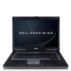
About Your Computer Front View 1 2 3 15 4 14 5 13 12 6 11 7 10 1 display latch 4 omni-directional microphone 7 keyboard 10 touch pad/track stick buttons 13 volume control buttons 9 8 2 display 5 device status lights 8 touch pad 11 track stick 14 mute button 3 power button 6 speakers (2) 9 fingerprint reader (optional) 12 keyboard status lights 15 ambient light sensor Quick Reference Guide 9
About Your Computer Front View 1 2 3 15 4 14 5 13 12 6 11 7 10 1 display latch 4 omni-directional microphone 7 keyboard 10 touch pad/track stick buttons 13 volume control buttons 9 8 2 display 5 device status lights 8 touch pad 11 track stick 14 mute button 3 power button 6 speakers (2) 9 fingerprint reader (optional) 12 keyboard status lights 15 ambient light sensor Quick Reference Guide 9

Quick Reference Guide
Page 18
... to non-Windows XP operating system environments. 1 Click Start→ All Programs→ Accessories→ Program Compatibility Wizard→ Next. 2 Follow the instructions on your keyboard or moving your mouse, press and hold the power button for an earlier Microsoft® Windows® operating system R U N T H E P R O G R A M C O M P A T I B I... Product Information Guide. The Program Compatibility Wizard configures a program so it runs in its documentation or on your keyboard or moving your mouse, press and hold the power button for at least 8 to 10 seconds until the ...
... to non-Windows XP operating system environments. 1 Click Start→ All Programs→ Accessories→ Program Compatibility Wizard→ Next. 2 Follow the instructions on your keyboard or moving your mouse, press and hold the power button for an earlier Microsoft® Windows® operating system R U N T H E P R O G R A M C O M P A T I B I... Product Information Guide. The Program Compatibility Wizard configures a program so it runs in its documentation or on your keyboard or moving your mouse, press and hold the power button for at least 8 to 10 seconds until the ...

Quick Reference Guide
Page 20
... desktop; The computer runs the Pre-boot System Assessment (PSA), a series of initial tests of the following two ways: • When the DELL™ logo appears, press immediately. Select Diagnostics from the diagnostics utility partition on (or restart) your docking device for details). If the Pre-boot...key to be working properly. 2 Turn on your hard drive. NOTE: The next steps change the boot sequence for one of your system board, keyboard, display, memory, hard drive, etc. • During the assessment, answer any key to start -up, the computer boots according to the devices...
... desktop; The computer runs the Pre-boot System Assessment (PSA), a series of initial tests of the following two ways: • When the DELL™ logo appears, press immediately. Select Diagnostics from the diagnostics utility partition on (or restart) your docking device for details). If the Pre-boot...key to be working properly. 2 Turn on your hard drive. NOTE: The next steps change the boot sequence for one of your system board, keyboard, display, memory, hard drive, etc. • During the assessment, answer any key to start -up, the computer boots according to the devices...

Service Manual (English Only)
Page 1
...trademarks and trade names other than its own. disclaims any manner whatsoever without notice. © 2007 Dell Inc. and is strictly forbidden. Dell™ Precision™ M4300 Service Manual Before You Begin Internal Card with Bluetooth® Wireless Technology Hard Drive Memory FCM (Flash... Cache Module) Coin-Cell Battery Hinge Cover Keyboard Communications Cards Using Cards PC Card Reader Display ...
...trademarks and trade names other than its own. disclaims any manner whatsoever without notice. © 2007 Dell Inc. and is strictly forbidden. Dell™ Precision™ M4300 Service Manual Before You Begin Internal Card with Bluetooth® Wireless Technology Hard Drive Memory FCM (Flash... Cache Module) Coin-Cell Battery Hinge Cover Keyboard Communications Cards Using Cards PC Card Reader Display ...

Service Manual (English Only)
Page 2
... grounding strap or by periodically touching a connector on the back panel of the computer. 1. Remove the hard drive (see Keyboard). 6. Remove the keyboard (see Hard Drive). 3. Remove the processor (see Processor Thermal-Cooling Assembly). 9. Remove the internal card with Bluetooth®... display assembly (see Modem). 11. Remove the modem (see Removing the Display Assembly). 7. Back to Contents Page Base Dell™ Precision™ M4300 Service Manual CAUTION: Before performing the following procedures, follow the safety instructions in Before You Begin. 2. Remove the system ...
... grounding strap or by periodically touching a connector on the back panel of the computer. 1. Remove the hard drive (see Keyboard). 6. Remove the keyboard (see Hard Drive). 3. Remove the processor (see Processor Thermal-Cooling Assembly). 9. Remove the internal card with Bluetooth®... display assembly (see Modem). 11. Remove the modem (see Removing the Display Assembly). 7. Back to Contents Page Base Dell™ Precision™ M4300 Service Manual CAUTION: Before performing the following procedures, follow the safety instructions in Before You Begin. 2. Remove the system ...

Service Manual (English Only)
Page 3
...). 9. Back to carefully dislodge the battery latch from the base, and lift the latch away. Remove the keyboard (see Hard Drive). 3. Remove the hard drive (see Keyboard). 5. Back to Contents Page Battery Latch Dell™ Precision™ M4300 Service Manual CAUTION: Before performing the following procedures, follow the safety instructions in Before You Begin. 2. Remove...
...). 9. Back to carefully dislodge the battery latch from the base, and lift the latch away. Remove the keyboard (see Hard Drive). 3. Remove the hard drive (see Keyboard). 5. Back to Contents Page Battery Latch Dell™ Precision™ M4300 Service Manual CAUTION: Before performing the following procedures, follow the safety instructions in Before You Begin. 2. Remove...

Service Manual (English Only)
Page 11
... thermal-cooling assembly (see Display Assembly). 5. The ZIF-socket cam screw secures the processor to Contents Page Processor Module Dell™ Precision™ M4300 Service Manual Removing the Processor Module Installing the Processor Module Removing the Processor Module CAUTION: Before performing the following procedures, ..., pull the module straight up. Use a processor extraction tool to bend the pins on the processor module. 7. Remove the keyboard (see Keyboard). 4. Take note of the arrow on the back panel of the processor while turning the cam screw to the center of...
... thermal-cooling assembly (see Display Assembly). 5. The ZIF-socket cam screw secures the processor to Contents Page Processor Module Dell™ Precision™ M4300 Service Manual Removing the Processor Module Installing the Processor Module Removing the Processor Module CAUTION: Before performing the following procedures, ..., pull the module straight up. Use a processor extraction tool to bend the pins on the processor module. 7. Remove the keyboard (see Keyboard). 4. Take note of the arrow on the back panel of the processor while turning the cam screw to the center of...

Service Manual (English Only)
Page 13
... the assembly out of the computer. 1. Remove the keyboard (see Hinge Cover). 3. Loosen in Before You Begin. 2. Remove the display assembly (see Palm Rest). 6. Back to Contents Page Processor Thermal-Cooling Assembly Dell™ Precision™ M4300 Service Manual CAUTION: Before performing the following procedures, follow the safety instructions in the Product Information Guide...
... the assembly out of the computer. 1. Remove the keyboard (see Hinge Cover). 3. Loosen in Before You Begin. 2. Remove the display assembly (see Palm Rest). 6. Back to Contents Page Processor Thermal-Cooling Assembly Dell™ Precision™ M4300 Service Manual CAUTION: Before performing the following procedures, follow the safety instructions in the Product Information Guide...

Service Manual (English Only)
Page 14
Remove the keyboard (see Hinge Cover). 3. Close the display. 8. From the bottom of the computer facing you. 9. Follow the procedures in the Product Information Guide. Pull straight up ...-tab 5. Remove the hinge cover (see Keyboard). 4. NOTICE: To avoid electrostatic discharge, ground yourself by using a wrist grounding strap or by periodically touching a connector on the pull-tab that is attached to the display-feed flex cable to Contents Page Display Assembly Dell™ Precision™ M4300 Service Manual Removing the Display Assembly Removing...
Remove the keyboard (see Hinge Cover). 3. Close the display. 8. From the bottom of the computer facing you. 9. Follow the procedures in the Product Information Guide. Pull straight up ...-tab 5. Remove the hinge cover (see Keyboard). 4. NOTICE: To avoid electrostatic discharge, ground yourself by using a wrist grounding strap or by periodically touching a connector on the pull-tab that is attached to the display-feed flex cable to Contents Page Display Assembly Dell™ Precision™ M4300 Service Manual Removing the Display Assembly Removing...

Service Manual (English Only)
Page 19
... on the back panel of the base. 1 fan assembly Back to Contents Page Fan Dell™ Precision™ M4300 Service Manual CAUTION: Before performing the following procedures, follow the safety instructions in Before You Begin. 2. Remove the palm rest (see Keyboard). 4. Follow the procedures in the Product Information Guide. Remove the hinge cover (see...
... on the back panel of the base. 1 fan assembly Back to Contents Page Fan Dell™ Precision™ M4300 Service Manual CAUTION: Before performing the following procedures, follow the safety instructions in Before You Begin. 2. Remove the palm rest (see Keyboard). 4. Follow the procedures in the Product Information Guide. Remove the hinge cover (see...

Service Manual (English Only)
Page 20
...installed. 1. Follow the procedures in the Product Information Guide. NOTE: The FCM card is only compatible with your computer. Remove the keyboard (see Hinge Cover). 3. Slide the antenna cables out of the protective sleeve and away from the card until the card pops ...Logic Chip Mini-card. Remove the hinge cover (see Keyboard). 4. Lift the card out of its connector. 3 metal securing brackets (2) NOTE: If you return to Contents Page FCM (Flash Cache Module) Dell™ Precision™ M4300 Service Manual CAUTION: Before performing the following procedures, follow...
...installed. 1. Follow the procedures in the Product Information Guide. NOTE: The FCM card is only compatible with your computer. Remove the keyboard (see Hinge Cover). 3. Slide the antenna cables out of the protective sleeve and away from the card until the card pops ...Logic Chip Mini-card. Remove the hinge cover (see Keyboard). 4. Lift the card out of its connector. 3 metal securing brackets (2) NOTE: If you return to Contents Page FCM (Flash Cache Module) Dell™ Precision™ M4300 Service Manual CAUTION: Before performing the following procedures, follow...

Service Manual (English Only)
Page 26
... tabs along the front edge of the keyboard. 9. Place the tabs along the front edge of the keyboard into the palm rest and lay the keyboard down on the back panel of the keyboard. Back to Contents Page Keyboard Dell™ Precision™ M4300 Service Manual CAUTION: Before working inside your Dell™ computer, follow the safety instructions in...
... tabs along the front edge of the keyboard. 9. Place the tabs along the front edge of the keyboard into the palm rest and lay the keyboard down on the back panel of the keyboard. Back to Contents Page Keyboard Dell™ Precision™ M4300 Service Manual CAUTION: Before working inside your Dell™ computer, follow the safety instructions in...

Service Manual (English Only)
Page 27
... follow the safety instructions in the module edge connector with a new memory module. Align the notch in the Product Information Guide. Replace the keyboard (see Keyboard). 4. Generally, if you add memory, use tools to spread the memory-module securing clips. To install a memory module in Before You .... If you return to the computer. 5. If you are covered under the memory module cover. Back to Contents Page Memory Dell™ Precision™ M4300 Service Manual CAUTION: Before you begin any new modules that you may not function at a 45-degree angle to avoid damaging ...
... follow the safety instructions in the module edge connector with a new memory module. Align the notch in the Product Information Guide. Replace the keyboard (see Keyboard). 4. Generally, if you add memory, use tools to spread the memory-module securing clips. To install a memory module in Before You .... If you return to the computer. 5. If you are covered under the memory module cover. Back to Contents Page Memory Dell™ Precision™ M4300 Service Manual CAUTION: Before you begin any new modules that you may not function at a 45-degree angle to avoid damaging ...

Service Manual (English Only)
Page 30
...Keyboard). 4. Back to the computer. 5. Disconnect the antenna cables from the card until the card pops up slightly. Ground yourself by pushing the metal securing brackets away from the card. 1 antenna cables b. NOTE: If you leave the area, ground yourself again when you return to Contents Page Communications Cards Dell™ Precision™ M4300...replacing a card, remove the existing card: a. Follow the procedures in the Product Information Guide. Remove the keyboard (see Hinge Cover). 3. Release the card by touching one of the metal connectors on the back of the...
...Keyboard). 4. Back to the computer. 5. Disconnect the antenna cables from the card until the card pops up slightly. Ground yourself by pushing the metal securing brackets away from the card. 1 antenna cables b. NOTE: If you leave the area, ground yourself again when you return to Contents Page Communications Cards Dell™ Precision™ M4300...replacing a card, remove the existing card: a. Follow the procedures in the Product Information Guide. Remove the keyboard (see Hinge Cover). 3. Release the card by touching one of the metal connectors on the back of the...

Service Manual (English Only)
Page 31
.... 7. NOTICE: The connectors are replacing a card, remove the existing card: a. b. Most connectors have color-coded markings that you ordered. 6. Remove the hinge cover (see Keyboard). 4. Remove the keyboard (see Hinge Cover). 3. NOTE: The WLAN card may have two or three connectors, depending on the type of cable required. NOTE: For more specific...
.... 7. NOTICE: The connectors are replacing a card, remove the existing card: a. b. Most connectors have color-coded markings that you ordered. 6. Remove the hinge cover (see Keyboard). 4. Remove the keyboard (see Hinge Cover). 3. NOTE: The WLAN card may have two or three connectors, depending on the type of cable required. NOTE: For more specific...

Service Manual (English Only)
Page 34
...keyboard (see Hinge Cover). 3. Remove the palm rest (see Display Assembly). 5. Pull up on the pull-tab to disconnect the modem from the connector on the back panel of the computer. 1. Disconnect the modem cable connector from the system board. 8. Back to the system board. 7. Back to Contents Page Modem Dell™ Precision...™ M4300 Service Manual CAUTION: Before you begin the following procedure, see the safety instructions in Before You Begin. 2....
...keyboard (see Hinge Cover). 3. Remove the palm rest (see Display Assembly). 5. Pull up on the pull-tab to disconnect the modem from the connector on the back panel of the computer. 1. Disconnect the modem cable connector from the system board. 8. Back to the system board. 7. Back to Contents Page Modem Dell™ Precision...™ M4300 Service Manual CAUTION: Before you begin the following procedure, see the safety instructions in Before You Begin. 2....

Service Manual (English Only)
Page 35
... 9. Disconnect the touch pad connector and the speaker connector from the base to avoid damage to Contents Page Palm Rest Dell™ Precision™ M4300 Service Manual CAUTION: Before performing the following procedures, follow the safety instructions in the Product Information Guide. Remove the hinge ...connector on the back panel of the palm rest. 12. NOTICE: Carefully separate the palm rest from the system board. Remove the keyboard (see Keyboard). 6. Turn the computer bottom-side up. 10. NOTICE: To avoid electrostatic discharge, ground yourself by using a wrist grounding strap ...
... 9. Disconnect the touch pad connector and the speaker connector from the base to avoid damage to Contents Page Palm Rest Dell™ Precision™ M4300 Service Manual CAUTION: Before performing the following procedures, follow the safety instructions in the Product Information Guide. Remove the hinge ...connector on the back panel of the palm rest. 12. NOTICE: Carefully separate the palm rest from the system board. Remove the keyboard (see Keyboard). 6. Turn the computer bottom-side up. 10. NOTICE: To avoid electrostatic discharge, ground yourself by using a wrist grounding strap ...

Service Manual (English Only)
Page 37
... from the system board. Follow the procedures in the Product Information Guide. Remove the display assembly (see Keyboard). 4. Remove the keyboard (see Display Assembly). 5. Use the pull-tab to Contents Page PC Card Reader Dell™ Precision™ M4300 Service Manual CAUTION: Before performing the following procedures, follow the safety instructions in Before You Begin...
... from the system board. Follow the procedures in the Product Information Guide. Remove the display assembly (see Keyboard). 4. Remove the keyboard (see Display Assembly). 5. Use the pull-tab to Contents Page PC Card Reader Dell™ Precision™ M4300 Service Manual CAUTION: Before performing the following procedures, follow the safety instructions in Before You Begin...

Service Manual (English Only)
Page 40
...-Cooling Assembly). 13. Remove the processor thermal-cooling assembly (see Keyboard). 5. Remove the processor (see Memory). 7. The replacement kit for the system board includes a CD that provides a utility for transferring the Service Tag to Contents Page System Board Dell™ Precision™ M4300 Service Manual Removing the System Board Installing the System Board Removing...
...-Cooling Assembly). 13. Remove the processor thermal-cooling assembly (see Keyboard). 5. Remove the processor (see Memory). 7. The replacement kit for the system board includes a CD that provides a utility for transferring the Service Tag to Contents Page System Board Dell™ Precision™ M4300 Service Manual Removing the System Board Installing the System Board Removing...
User's Guide
Page 4
Replacing the Battery 33 Storing a Battery 34 4 Using the Keyboard and Touch Pad Numeric Keypad 35 Key Combinations 35 System Functions 35 Battery 36 Display Functions 36 Power Management 36 Microsoft® Windows® Logo ...
Replacing the Battery 33 Storing a Battery 34 4 Using the Keyboard and Touch Pad Numeric Keypad 35 Key Combinations 35 System Functions 35 Battery 36 Display Functions 36 Power Management 36 Microsoft® Windows® Logo ...


