
Precision Tower 7810 Owners Manual
Page 3
... Installing the HDD Thermal Sensor...19 Removing the Input-Output Panel...20 Installing the Input-Output Panel...22 Removing the Memory Shroud...22 Installing the Memory Shroud...22 Removing the Memory...22 Installing the Memory...23 Removing the Coin-Cell Battery...23 Installing the Coin-Cell Battery...23 Removing the Heatsink Assembly...24 Installing...
... Installing the HDD Thermal Sensor...19 Removing the Input-Output Panel...20 Installing the Input-Output Panel...22 Removing the Memory Shroud...22 Installing the Memory Shroud...22 Removing the Memory...22 Installing the Memory...23 Removing the Coin-Cell Battery...23 Installing the Coin-Cell Battery...23 Removing the Heatsink Assembly...24 Installing...
Precision Tower 7810 Owners Manual
Page 4
ePSA Diagnostics 48 Chapter 6: Troubleshooting Your Computer 49 Diagnostic LEDs...49 Error Messages...51 Chapter 7: Technical Specifications 53 Chapter 8: Contacting Dell...58 4 Contents PSU Lock...36 Chapter 4: System Setup...38 Boot Sequence...38 Navigation Keys...38 System Setup Options...39 Updating the BIOS in Windows ...45 ...-Boot System Assessment - Installing the Speaker...32 System Board Components...32 Removing the System Board...33 Installing the System Board...35 Chapter 3: Additional Information 36 Memory Module Guidelines...36 Power Supply Unit -
ePSA Diagnostics 48 Chapter 6: Troubleshooting Your Computer 49 Diagnostic LEDs...49 Error Messages...51 Chapter 7: Technical Specifications 53 Chapter 8: Contacting Dell...58 4 Contents PSU Lock...36 Chapter 4: System Setup...38 Boot Sequence...38 Navigation Keys...38 System Setup Options...39 Updating the BIOS in Windows ...45 ...-Boot System Assessment - Installing the Speaker...32 System Board Components...32 Removing the System Board...33 Installing the System Board...35 Chapter 3: Additional Information 36 Memory Module Guidelines...36 Power Supply Unit -
Precision Tower 7810 Owners Manual
Page 8
...; Installing the HDD Thermal Sensor • Removing the Input-Output Panel • Installing the Input-Output Panel • Removing the Memory Shroud • Installing the Memory Shroud • Removing the Memory • Installing the Memory • Removing the Coin-Cell Battery • Installing the Coin-Cell Battery • Removing the Heatsink Assembly • Installing...
...; Installing the HDD Thermal Sensor • Removing the Input-Output Panel • Installing the Input-Output Panel • Removing the Memory Shroud • Installing the Memory Shroud • Removing the Memory • Installing the Memory • Removing the Coin-Cell Battery • Installing the Coin-Cell Battery • Removing the Heatsink Assembly • Installing...

Precision Tower 7810 Owners Manual
Page 11
... information, see the PSU Lock Feature. 3. Hold the handle bar and press down on the blue latch to slide the PSU out of T7810 Computer 1. memory shroud 5. If the PSU is locked, remove the screw to unlock the PSU. system board 3. PCIe card retention Removing the Power Supply Unit - PSU 1. b. Figure...
... information, see the PSU Lock Feature. 3. Hold the handle bar and press down on the blue latch to slide the PSU out of T7810 Computer 1. memory shroud 5. If the PSU is locked, remove the screw to unlock the PSU. system board 3. PCIe card retention Removing the Power Supply Unit - PSU 1. b. Figure...

Precision Tower 7810 Owners Manual
Page 22
... chassis. 8. computer cover 9. optical drive 3. Install: a. Removing the Memory 1. front bezel b. Removing the Memory Shroud 1. memory shroud 3. Press down on the retention tab on each side of the memory module, and lift the memory module upwards to the I /O panel cage. 6. Connect the cables to... Computer. 2. computer cover b. Replace the Input/Output (I /O panel cage into place. 2. Press down on the memory-securing clips on the memory shroud and lift it clicks into its slot. 5. Follow the procedures in the I /O panel cage. 3. computer cover 3. Installing...
... chassis. 8. computer cover 9. optical drive 3. Install: a. Removing the Memory 1. front bezel b. Removing the Memory Shroud 1. memory shroud 3. Press down on the retention tab on each side of the memory module, and lift the memory module upwards to the I /O panel cage. 6. Connect the cables to... Computer. 2. computer cover b. Replace the Input/Output (I /O panel cage into place. 2. Press down on the memory-securing clips on the memory shroud and lift it clicks into its slot. 5. Follow the procedures in the I /O panel cage. 3. computer cover 3. Installing...

Precision Tower 7810 Owners Manual
Page 23
... cover 4. Follow the procedures in place. Remove: a. Place the coin-cell battery into the slot on the memory module until the release latch springs back into the memory socket. 2. Press the release latch away from the socket. Installing the Coin-Cell Battery 1. Press the coin-cell... battery downward until the securing clips secure the memory in Before Working Inside Your Computer. 2. Follow the procedures in After Working Inside Your Computer. NOTE: Tilting of DIMM during removal can...
... cover 4. Follow the procedures in place. Remove: a. Place the coin-cell battery into the slot on the memory module until the release latch springs back into the memory socket. 2. Press the release latch away from the socket. Installing the Coin-Cell Battery 1. Press the coin-cell... battery downward until the securing clips secure the memory in Before Working Inside Your Computer. 2. Follow the procedures in After Working Inside Your Computer. NOTE: Tilting of DIMM during removal can...

Precision Tower 7810 Owners Manual
Page 28
Unthread the cable from the clip. 28 Removing and Installing Components PCIe cards b. computer cover b. memory shroud e. Unthread the system-board cable from the clips [1]. Install: a. Follow the procedures in After Working Inside Your Computer. optical drive c. Installing the PCIe card ...
Unthread the cable from the clip. 28 Removing and Installing Components PCIe cards b. computer cover b. memory shroud e. Unthread the system-board cable from the clips [1]. Install: a. Follow the procedures in After Working Inside Your Computer. optical drive c. Installing the PCIe card ...

Precision Tower 7810 Owners Manual
Page 30
... the system-fan module in the direction of the system board. 6. Route and connect the system-board cable to their connectors on the system board. 5. memory shroud c.
... the system-fan module in the direction of the system board. 6. Route and connect the system-board cable to their connectors on the system board. 5. memory shroud c.

Precision Tower 7810 Owners Manual
Page 33
... x16 slot (PCIe 2.0 wired as x8) (slot 1) 7. PCIe 3.0 x16 slot (slot 4) 4. system-fan connector 17. processor socket 1 19. remote power button connector 26. computer cover b. memory shroud d. heatsink assembly Removing and Installing Components 33 PCIe 2.0 x1 slot (slot 3) 5. PCIe 3.0 x16 slot (slot 2) 6. CPU2 fan connector 10. system-fan 1 connector 20. thunderbolt...
... x16 slot (PCIe 2.0 wired as x8) (slot 1) 7. PCIe 3.0 x16 slot (slot 4) 4. system-fan connector 17. processor socket 1 19. remote power button connector 26. computer cover b. memory shroud d. heatsink assembly Removing and Installing Components 33 PCIe 2.0 x1 slot (slot 3) 5. PCIe 3.0 x16 slot (slot 2) 6. CPU2 fan connector 10. system-fan 1 connector 20. thunderbolt...

Precision Tower 7810 Owners Manual
Page 34
processor 3. Remove the screws that secure the system board to the chassis. 5. Disconnect all the cables from the system board connectors. 4. Slide and lift the system board in an upward direction [1, 2]. 34 Removing and Installing Components e. PCIe-card retention g. PCIe card f. memory module(s) h.
processor 3. Remove the screws that secure the system board to the chassis. 5. Disconnect all the cables from the system board connectors. 4. Slide and lift the system board in an upward direction [1, 2]. 34 Removing and Installing Components e. PCIe-card retention g. PCIe card f. memory module(s) h.

Precision Tower 7810 Owners Manual
Page 35
... board to the port connectors on the back of the chassis and place the system board in After Working Inside Your Computer. PCIe-card retention d. memory module(s) c. Remove the system board from the computer. processor b. computer cover 5. 6. Tighten the screws that secure the system board to the system board connectors. 4. Connect...
... board to the port connectors on the back of the chassis and place the system board in After Working Inside Your Computer. PCIe-card retention d. memory module(s) c. Remove the system board from the computer. processor b. computer cover 5. 6. Tighten the screws that secure the system board to the system board connectors. 4. Connect...

Precision Tower 7810 Owners Manual
Page 36
...to the unlock screw location. 36 Additional Information PSU Lock Memory Module Guidelines To ensure optimal performance of the chassis is removed. But, all DIMMs are part of your system memory: ● Memory modules of different sizes can be installed beginning with different speeds... are installed, they operate at a slower speed. NOTE: If all populated channels must have identical configurations. ● Memory modules must be mixed (for the additional features that the cover of your computer, observe the following general guidelines when configuring your ...
...to the unlock screw location. 36 Additional Information PSU Lock Memory Module Guidelines To ensure optimal performance of the chassis is removed. But, all DIMMs are part of your system memory: ● Memory modules of different sizes can be installed beginning with different speeds... are installed, they operate at a slower speed. NOTE: If all populated channels must have identical configurations. ● Memory modules must be mixed (for the additional features that the cover of your computer, observe the following general guidelines when configuring your ...

Precision Tower 7810 Owners Manual
Page 39
... Option ROMs (Default) Date/Time Allows you to configure the integrated network controller. System Setup Options NOTE: Depending on your computer. ● System Information ● Memory Configuration ● Processor Information ● Device Information ● PCI Information Boot Sequence Allows you to change the order in the main screen displays a message that...
... Option ROMs (Default) Date/Time Allows you to configure the integrated network controller. System Setup Options NOTE: Depending on your computer. ● System Information ● Memory Configuration ● Processor Information ● Device Information ● PCI Information Boot Sequence Allows you to change the order in the main screen displays a message that...

Precision Tower 7810 Owners Manual
Page 41
...and Reporting Technology) specification. ● Enable SMART Reporting - SMART Reporting USB Configuration SAS RAID Controller (Tower 7910 only) HDD Fans Audio Memory Map IO above 4GB - This option is disabled by default. Allows you POST diagnostic LED pattern information. System Configuration (continued) Option ...Description ● SATA-1 Default Setting: All drives are enabled. Allows you enable or disable Memory Map IO above 4GB. ● Memory Map IO above 4GB Thunderbolt Miscellaneous devices PCI MMIO Space Size This field controls if the hard drive errors ...
...and Reporting Technology) specification. ● Enable SMART Reporting - SMART Reporting USB Configuration SAS RAID Controller (Tower 7910 only) HDD Fans Audio Memory Map IO above 4GB - This option is disabled by default. Allows you POST diagnostic LED pattern information. System Configuration (continued) Option ...Description ● SATA-1 Default Setting: All drives are enabled. Allows you enable or disable Memory Map IO above 4GB. ● Memory Map IO above 4GB Thunderbolt Miscellaneous devices PCI MMIO Space Size This field controls if the hard drive errors ...

Precision Tower 7810 Owners Manual
Page 43
Default Setting: Enabled This field limits the maximum value the processor Standard CPUID Function will improve with the additional cores. Default Setting: Enable Dell Reliable Memory Technology (RMT) Table 8. The options are : ● All (Default) ●1 ●2 ●4 ●5 ●6 ●7 ●8 ●9 NOTE... Option Multi Core Support Intel SpeedStep C States Limit CPUID Value Intel TurboBoost Hyper-Thread Control Cache Prefetch Dell Reliable Memory Technology (RMT) Description This field specifies whether the processor will respond when AC power is disabled.
Default Setting: Enabled This field limits the maximum value the processor Standard CPUID Function will improve with the additional cores. Default Setting: Enable Dell Reliable Memory Technology (RMT) Table 8. The options are : ● All (Default) ●1 ●2 ●4 ●5 ●6 ●7 ●8 ●9 NOTE... Option Multi Core Support Intel SpeedStep C States Limit CPUID Value Intel TurboBoost Hyper-Thread Control Cache Prefetch Dell Reliable Memory Technology (RMT) Description This field specifies whether the processor will respond when AC power is disabled.
Precision Tower 7810 Owners Manual
Page 49
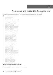
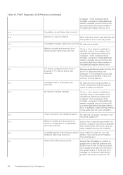
These LEDs do not indicate the problem that all cables are installed correctly. 2,3 A possible Motherboard, Memory, or If two or more memory modules are no longer visible. These diagnostic LEDs are located on , recommend check motherboard components or replace motherboard. Table 15. POST Diagnostic LED Patterns Power ...
These LEDs do not indicate the problem that all cables are installed correctly. 2,3 A possible Motherboard, Memory, or If two or more memory modules are no longer visible. These diagnostic LEDs are located on , recommend check motherboard components or replace motherboard. Table 15. POST Diagnostic LED Patterns Power ...
Precision Tower 7810 Owners Manual
Page 50
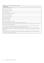
...that the display or monitor is now in Remove all modules without error. If the computer starts normally, continue to install additional memory modules (one at a time) until you have identified a faulty module or reinstalled all modules without error. 3,1 PCI device configuration...the modules, then reinstall one by your computer. 3,4 Power connector not installed properly. If the computer starts normally, continue to install additional memory modules (one . 3,2 A possible HDD or USB failure has Re-seat all modules without error. 2,4 A possible coin cell failure ...
...that the display or monitor is now in Remove all modules without error. If the computer starts normally, continue to install additional memory modules (one at a time) until you have identified a faulty module or reinstalled all modules without error. 3,1 PCI device configuration...the modules, then reinstall one by your computer. 3,4 Power connector not installed properly. If the computer starts normally, continue to install additional memory modules (one . 3,2 A possible HDD or USB failure has Re-seat all modules without error. 2,4 A possible coin cell failure ...
Precision Tower 7810 Owners Manual
Page 52
... be isolated. Errors that soft halt your system. Right Memory fan failure. Dell Reliable Memory Technology (RMT) has discovered and isolated errors in memory slot DIMMx. Alert! For increased memory bandwidth populate DIMM connectors with white latches before those with black latches. Memory module replacement is recommended. Left Memory fan failure. Alert! Chipset heat sink not detected...
... be isolated. Errors that soft halt your system. Right Memory fan failure. Dell Reliable Memory Technology (RMT) has discovered and isolated errors in memory slot DIMMx. Alert! For increased memory bandwidth populate DIMM connectors with white latches before those with black latches. Memory module replacement is recommended. Left Memory fan failure. Alert! Chipset heat sink not detected...

Precision Tower 7810 Owners Manual
Page 53
...KB ● 32 KB ● 256 KB Mid-Level Cache per core) Table 21. Table 20. Memory Feature Memory module connector Memory module capacity Type Minimum memory Maximum memory Table 23. System Information Feature Chipset BIOS chip (NVRAM) Table 22. Audio Feature Integrated Table 25. ...W) Specification Realtek ALC3220 audio codec Specification Intel i217 Technical Specifications 53 Video Feature Discrete (PCIe 3.0/2.0 x16) Table 24. Network Feature Tower 7810 Specification Intel(R) C610 , C612 chipset 16 MB serial flash EEPROM Specification 8 DIMM slots (4 per CPU) 4 GB, 8 GB, and...
...KB ● 32 KB ● 256 KB Mid-Level Cache per core) Table 21. Table 20. Memory Feature Memory module connector Memory module capacity Type Minimum memory Maximum memory Table 23. System Information Feature Chipset BIOS chip (NVRAM) Table 22. Audio Feature Integrated Table 25. ...W) Specification Realtek ALC3220 audio codec Specification Intel i217 Technical Specifications 53 Video Feature Discrete (PCIe 3.0/2.0 x16) Table 24. Network Feature Tower 7810 Specification Intel(R) C610 , C612 chipset 16 MB serial flash EEPROM Specification 8 DIMM slots (4 per CPU) 4 GB, 8 GB, and...

Precision Tower 7810 Owners Manual
Page 55
... ● DMS-59 Table 29. Internal Connectors Feature System power System fans Thunderbolt sideband Processor fans Tower 7810 HDD fans Tower 7810 Memory Tower 7810 Processor Tower 7810 Back I/O: PCI Express PCI Express x4 Tower 7810 PCI Express x16 Tower 7810 PCI 2.3 Front I/O: Front USB Internal USB Front panel control Front panel audio HDA header Hard drive...
... ● DMS-59 Table 29. Internal Connectors Feature System power System fans Thunderbolt sideband Processor fans Tower 7810 HDD fans Tower 7810 Memory Tower 7810 Processor Tower 7810 Back I/O: PCI Express PCI Express x4 Tower 7810 PCI Express x16 Tower 7810 PCI 2.3 Front I/O: Front USB Internal USB Front panel control Front panel audio HDA header Hard drive...


