
Service Manual
Page 1
COLOR MONITOR L29K-A D99 CHASSIS SPECIFICATIONS Picture tube 0.24-0.25 mm aperture grill pitch 17 inches measured diagonally 90-degree deflection Video image area (16" maximum viewing image) Approx. 326 X 243 mm (w/h) (127/8 x 95/8 inches) Resolution Horizontal: Max. 1280 dots ... V, 50/60 Hz, 1.7A 220 to 240V, 50/60Hz, 0.9A 414 x 404 x 420mm (w/h/d) (161/4 x 157/8 x 161/2 inches) Approx. 18.8 kg (41 lbs. 8 oz.) Design and specifications are subject to change without notice. SERVICE MANUAL P780 P780 Equator Model Japan Model N. Hemisphere Model Chassis No. Hemisphere Model S.
COLOR MONITOR L29K-A D99 CHASSIS SPECIFICATIONS Picture tube 0.24-0.25 mm aperture grill pitch 17 inches measured diagonally 90-degree deflection Video image area (16" maximum viewing image) Approx. 326 X 243 mm (w/h) (127/8 x 95/8 inches) Resolution Horizontal: Max. 1280 dots ... V, 50/60 Hz, 1.7A 220 to 240V, 50/60Hz, 0.9A 414 x 404 x 420mm (w/h/d) (161/4 x 157/8 x 161/2 inches) Approx. 18.8 kg (41 lbs. 8 oz.) Design and specifications are subject to change without notice. SERVICE MANUAL P780 P780 Equator Model Japan Model N. Hemisphere Model Chassis No. Hemisphere Model S.

Service Manual
Page 2
....422 59.940 525 45 10 2 33 480 No Yes -/- P780 POWER MANAGEMENT The power saving mode complies with the VESA Display Power Management Signaling standard. Reactivation of the problem. Green and Orange...(0.5 second) Amber (0.5 second)/Off (1.5 second) Amber(0.5 second)/Off (0.5 second)/ Green (0.5 second)/Off (0.5 second) TIMING SPECIFICATION MODE Resolution (H x V) Dot Clock (MHz) HORIZONTAL Hor. Freq. (Hz) V-Total V-Blanking V-Front Porch V-Sync.....667 6.349 0.508 2.032 3.810 20.317 43.269 23.111 5.333 1.556 1.556 2.222 17.778 75.000 500 20 1 3 16 480 85.008 509 29 1 3 25 480 No Yes...
....422 59.940 525 45 10 2 33 480 No Yes -/- P780 POWER MANAGEMENT The power saving mode complies with the VESA Display Power Management Signaling standard. Reactivation of the problem. Green and Orange...(0.5 second) Amber (0.5 second)/Off (1.5 second) Amber(0.5 second)/Off (0.5 second)/ Green (0.5 second)/Off (0.5 second) TIMING SPECIFICATION MODE Resolution (H x V) Dot Clock (MHz) HORIZONTAL Hor. Freq. (Hz) V-Total V-Blanking V-Front Porch V-Sync.....667 6.349 0.508 2.032 3.810 20.317 43.269 23.111 5.333 1.556 1.556 2.222 17.778 75.000 500 20 1 3 16 480 85.008 509 29 1 3 25 480 No Yes...

Service Manual
Page 6
... 6 B/b buttons to normal viewing. • Resetting: If you finish adjusting the setting, press the MENU button to return to select a specific item. 4 Adjust the monitor setting using the reset function, see the "Resetting the Adjustments" section on the following pages in memory for the...5000K. Colors appear reddish if the temperature is low, and bluish if the temperature is stored in order. P780 - 6 - To adjust the monitor settings: 1 Press the MENU button to display the MENU OSD. 2 Highlight the desired OSD using the BRIGHTNESS buttons and press the MENU button again....
... 6 B/b buttons to normal viewing. • Resetting: If you finish adjusting the setting, press the MENU button to return to select a specific item. 4 Adjust the monitor setting using the reset function, see the "Resetting the Adjustments" section on the following pages in memory for the...5000K. Colors appear reddish if the temperature is low, and bluish if the temperature is stored in order. P780 - 6 - To adjust the monitor settings: 1 Press the MENU button to display the MENU OSD. 2 Highlight the desired OSD using the BRIGHTNESS buttons and press the MENU button again....

Service Manual
Page 7
... press the v/V buttons to highlight (OSD H POSITION). The HELP OSD appears on the screen. The INFORMATION OSD appears. P780 - 7 - The monitor is displayed on the screen. 2 Press the v/V buttons to highlight the desired adjustment item. Example of moire Adjusting the OSD Horizontal ... MENU RECOMMENDED RESOLUTION FLICKER THIN HORIZONTAL LINE DISTORTED SHAPE OUT OF FOCUS DISCOLORATION Customizing Your Monitor Resetting the adjustments Resetting a specific adjustment Navigate through the on . Press and hold the reset button for the current input signal Press the RESET button ...
... press the v/V buttons to highlight (OSD H POSITION). The HELP OSD appears on the screen. The INFORMATION OSD appears. P780 - 7 - The monitor is displayed on the screen. 2 Press the v/V buttons to highlight the desired adjustment item. Example of moire Adjusting the OSD Horizontal ... MENU RECOMMENDED RESOLUTION FLICKER THIN HORIZONTAL LINE DISTORTED SHAPE OUT OF FOCUS DISCOLORATION Customizing Your Monitor Resetting the adjustments Resetting a specific adjustment Navigate through the on . Press and hold the reset button for the current input signal Press the RESET button ...

Service Manual
Page 9
...humming sound or high frequency squeal Screen has scratches or smudges Visible signs of the glass, try cleaning the CRT screen Brightness Problems Picture too dim or too bright • Perform monitor reset • Adjust brightness &... Moiré (Thin Curvy Lines) Horizontal/Vertical Lines Sync Problems Audible Noise Problems CRT Scratched Safety Related Issues Intermittent Problems PRODUCT SPECIFIC SYMPTOMS SPECIFIC SYMPTOMS Two fine lines on the screen. This aperture grille allows more light to pass... general information about common monitor problems you might encounter. P780 - 9 -
...humming sound or high frequency squeal Screen has scratches or smudges Visible signs of the glass, try cleaning the CRT screen Brightness Problems Picture too dim or too bright • Perform monitor reset • Adjust brightness &... Moiré (Thin Curvy Lines) Horizontal/Vertical Lines Sync Problems Audible Noise Problems CRT Scratched Safety Related Issues Intermittent Problems PRODUCT SPECIFIC SYMPTOMS SPECIFIC SYMPTOMS Two fine lines on the screen. This aperture grille allows more light to pass... general information about common monitor problems you might encounter. P780 - 9 -

Service Manual
Page 12
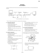
... apply sufficient amount of FBT (T501) and GND, and confirm that the raster fades out. Standard voltage: 180 ± 3.0 VDC RV501 - 12 - P780 SECTION 3 SAFETY RELATED ADJUSTMENTS When replacing parts shown in the table below, the following conditions: a) HV Regulator Check 1) Input white cross hatch signal. (fH... for one minute prior to recheck the High Voltage. 7) Verify the High Voltage as shown above (26.9 KV ± 0.4 KV) is within specification, put the RV cover on "D" and GND, and confirm that the HV Hold-Down circuit works. (Raster disappears) Apply DC Voltage: Less than 35...
... apply sufficient amount of FBT (T501) and GND, and confirm that the raster fades out. Standard voltage: 180 ± 3.0 VDC RV501 - 12 - P780 SECTION 3 SAFETY RELATED ADJUSTMENTS When replacing parts shown in the table below, the following conditions: a) HV Regulator Check 1) Input white cross hatch signal. (fH... for one minute prior to recheck the High Voltage. 7) Verify the High Voltage as shown above (26.9 KV ± 0.4 KV) is within specification, put the RV cover on "D" and GND, and confirm that the HV Hold-Down circuit works. (Raster disappears) Apply DC Voltage: Less than 35...
Service Manual
Page 13
... ~ 3 ) are necessary for the landing correction. 13. Adjust the contrast to "7". - 13 - Display the plain green pattern. 4. If the corner landing is out of specification, use a disk magnet for DAS adjustment. * Allow a 30 minute warm-up and down with white ...CRT face. 8. Display the all white pattern. 2. Convergence and V. Convergence Rough Adjustment 1. Set TLH plate to making the following adjustments: 4-1. Attach a wobbling coil to the specified position of landing checker to [b]. 3. Adjust top and bottom pin by pitching DY up period prior to zero position. 3. P780...
... ~ 3 ) are necessary for the landing correction. 13. Adjust the contrast to "7". - 13 - Display the plain green pattern. 4. If the corner landing is out of specification, use a disk magnet for DAS adjustment. * Allow a 30 minute warm-up and down with white ...CRT face. 8. Display the all white pattern. 2. Convergence and V. Convergence Rough Adjustment 1. Set TLH plate to making the following adjustments: 4-1. Attach a wobbling coil to the specified position of landing checker to [b]. 3. Adjust top and bottom pin by pitching DY up period prior to zero position. 3. P780...

Service Manual
Page 14
...Adjust YCH with white paint Zero Position NECK Ass'y 8. Vertical and Horizontal Position and Size Specification B b a a A b fH > 60kHz a = 2.0 mm b = 2.0 mm fH < kHz 2.4 mm 2.4 mm A B 234 312 4-6. Display crosshatch pattern with TLH plate. Adjust H.TILT with red and blue lines and black field. ...(V) and focus (H) for the entire screen. 16. Adjust V.TILT with XCV VR. P780 4. YCH movement 4-5. Adjust XCV with TLV VR. - 14 - Display crosshatch pattern with red and blue lines and black field. 5. Display crosshatch pattern with white lines and black field. 7.
...Adjust YCH with white paint Zero Position NECK Ass'y 8. Vertical and Horizontal Position and Size Specification B b a a A b fH > 60kHz a = 2.0 mm b = 2.0 mm fH < kHz 2.4 mm 2.4 mm A B 234 312 4-6. Display crosshatch pattern with TLH plate. Adjust H.TILT with red and blue lines and black field. ...(V) and focus (H) for the entire screen. 16. Adjust V.TILT with XCV VR. P780 4. YCH movement 4-5. Adjust XCV with TLV VR. - 14 - Display crosshatch pattern with red and blue lines and black field. 5. Display crosshatch pattern with white lines and black field. 7.

Service Manual
Page 15
... entire screen is within the specification. Vertical Convergence CCV-T-L-HI 13...entire screen is within the specification. 4-8. B. Vertical Convergence CCV...CBH-T-L-HI 9 MBH-T-L-HI 17 YBH-T-HI 5 10 CBH-T-R-...APH-R-HI 20 MBH-B-R-HI 6 YBH-B-HI 12 CBH-B-R-HI Adjust each misconvergence point in sequence. B. Convergence Specification C B A 312 mm 234 mm A Zone: Primary Mode H: < 0.25mm V: < 0.2mm ... Digital Convergence Adjustment Convergence (Low) Mode 1. Horizontal Convergence CBH-T-L-LO 9 MBH-T-L-LO 17 YBH-T-LO 5 10 CBH-T-R-LO 18 MBH-T-R-LO APH-L-LO 1 MBH-B-L-LO 19...
... entire screen is within the specification. Vertical Convergence CCV-T-L-HI 13...entire screen is within the specification. 4-8. B. Vertical Convergence CCV...CBH-T-L-HI 9 MBH-T-L-HI 17 YBH-T-HI 5 10 CBH-T-R-...APH-R-HI 20 MBH-B-R-HI 6 YBH-B-HI 12 CBH-B-R-HI Adjust each misconvergence point in sequence. B. Convergence Specification C B A 312 mm 234 mm A Zone: Primary Mode H: < 0.25mm V: < 0.2mm ... Digital Convergence Adjustment Convergence (Low) Mode 1. Horizontal Convergence CBH-T-L-LO 9 MBH-T-L-LO 17 YBH-T-LO 5 10 CBH-T-R-LO 18 MBH-T-R-LO APH-L-LO 1 MBH-B-L-LO 19...

