
Quick Reference Guide
Page 2
is subject to change without the written permission of Dell Inc.; Trademarks used in this text: Dell, OptiPlex, and the DELL logo are trademarks of Dell Inc. Information in this document to Microsoft® Windows® operating systems are registered trademarks of your computer. Microsoft and Windows are not applicable. NOTICE: A ...
is subject to change without the written permission of Dell Inc.; Trademarks used in this text: Dell, OptiPlex, and the DELL logo are trademarks of Dell Inc. Information in this document to Microsoft® Windows® operating systems are registered trademarks of your computer. Microsoft and Windows are not applicable. NOTICE: A ...

Quick Reference Guide
Page 3
... 16 Removing the Computer Cover 16 Inside View 17 Replacing the Computer Cover 18 Solving Problems 18 Dell Diagnostics 19 Power Supply Light 22 System Lights 22 Diagnostic Lights 23 Beep Codes 26 Running the Dell™ IDE Hard Drive Diagnostics 27 Resolving Software and Hardware Incompatibilities 27 Using Microsoft® Windows...
... 16 Removing the Computer Cover 16 Inside View 17 Replacing the Computer Cover 18 Solving Problems 18 Dell Diagnostics 19 Power Supply Light 22 System Lights 22 Diagnostic Lights 23 Beep Codes 26 Running the Dell™ IDE Hard Drive Diagnostics 27 Resolving Software and Hardware Incompatibilities 27 Using Microsoft® Windows...

Quick Reference Guide
Page 5
Dell OptiPlex™ User's Guide Microsoft® Windows® XP Help and Support Center 1 Click the Start button and click Help and Support. 2 Click User's and system ... Information Guide • How to remove and replace parts • Technical specifications • How to configure system settings • How to reinstall drivers, run the Dell Diagnostics, or access your computer. Finding Information What Are You Looking For? • A diagnostic program for my computer • Drivers for technicians or experienced users...
Dell OptiPlex™ User's Guide Microsoft® Windows® XP Help and Support Center 1 Click the Start button and click Help and Support. 2 Click User's and system ... Information Guide • How to remove and replace parts • Technical specifications • How to configure system settings • How to reinstall drivers, run the Dell Diagnostics, or access your computer. Finding Information What Are You Looking For? • A diagnostic program for my computer • Drivers for technicians or experienced users...

Quick Reference Guide
Page 6
... from technicians, and online courses • Community - The Express Service Code is customized for corporate, government, and education customers. support.dell.com NOTE: Select your call status and support history • Top technical issues for my computer • Frequently asked questions •...contract for components, such as memory, the hard drive, and the operating system • Customer Care - Online discussion with other Dell customers • Upgrades - Upgrade information for my computer Find It Here Service Tag and Microsoft Windows License These labels are located ...
... from technicians, and online courses • Community - The Express Service Code is customized for corporate, government, and education customers. support.dell.com NOTE: Select your call status and support history • Top technical issues for my computer • Frequently asked questions •...contract for components, such as memory, the hard drive, and the operating system • Customer Care - Online discussion with other Dell customers • Upgrades - Upgrade information for my computer Find It Here Service Tag and Microsoft Windows License These labels are located ...

Quick Reference Guide
Page 7
To reinstall your OptiPlex User's Guide for instructions. Your operating system product key is already installed on your Windows License label attached to your computer. Operating System CD The ...
To reinstall your OptiPlex User's Guide for instructions. Your operating system product key is already installed on your Windows License label attached to your computer. Operating System CD The ...

Quick Reference Guide
Page 8
NOTE: To ensure proper ventilation, do not block) 8 Quick Reference Guide mounting holes (2) www.dell.com | support.dell.com About Your Computer NOTE: If you want to orient your computer under a desk top or on contacting Dell, see your online User's Guide. To order the bracket, contact Dell. For information on a wall surface, use the optional wall- Front View microphone connector USB connectors (2) power light power button headphone connector hard-drive access light Side View vents (do not block) module bay vents (do not block the cooling vents. mount bracket.
NOTE: To ensure proper ventilation, do not block) 8 Quick Reference Guide mounting holes (2) www.dell.com | support.dell.com About Your Computer NOTE: If you want to orient your computer under a desk top or on contacting Dell, see your online User's Guide. To order the bracket, contact Dell. For information on a wall surface, use the optional wall- Front View microphone connector USB connectors (2) power light power button headphone connector hard-drive access light Side View vents (do not block) module bay vents (do not block the cooling vents. mount bracket.

Quick Reference Guide
Page 9
Back View cover release knob vents (do not block) diagnostic lights power connector Cable Cover and Power Adapter parallel link integrity light connector network adapter network activity light line-out connector line-in connector USB connectors (5) serial connector video connector Quick Reference Guide 9
Back View cover release knob vents (do not block) diagnostic lights power connector Cable Cover and Power Adapter parallel link integrity light connector network adapter network activity light line-out connector line-in connector USB connectors (5) serial connector video connector Quick Reference Guide 9

Quick Reference Guide
Page 10
... from being pulled, tangled, or stepped on. Determining Placement and Orientation of the Computer NOTICE: Do not place your monitor on page 15). www.dell.com | support.dell.com Setting Up Your Computer NOTICE: When setting up your computer, secure all cables toward the back of your work area to prevent the...
... from being pulled, tangled, or stepped on. Determining Placement and Orientation of the Computer NOTICE: Do not place your monitor on page 15). www.dell.com | support.dell.com Setting Up Your Computer NOTICE: When setting up your computer, secure all cables toward the back of your work area to prevent the...
Quick Reference Guide
Page 11
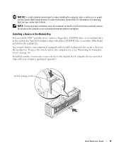
...ensure proper ventilation, place the computer at least 5 cm (2 inches) from a vertical surface. Installing a Device in the Module Bay You can install a Dell™ portable device such as a floppy drive, CD/DVD drive, or second hard drive in the module bay. As a security feature, your computer is... equipped with your online User's Guide. module locking switch Quick Reference Guide 11 To order the bracket, contact Dell. Your Dell computer ships with either a CD/DVD drive or an airbay (filler blank) installed in the module bay. Do not place the computer in...
...ensure proper ventilation, place the computer at least 5 cm (2 inches) from a vertical surface. Installing a Device in the Module Bay You can install a Dell™ portable device such as a floppy drive, CD/DVD drive, or second hard drive in the module bay. As a security feature, your computer is... equipped with your online User's Guide. module locking switch Quick Reference Guide 11 To order the bracket, contact Dell. Your Dell computer ships with either a CD/DVD drive or an airbay (filler blank) installed in the module bay. Do not place the computer in...

Quick Reference Guide
Page 12
... the Product Information Guide. Voltage from telephone communications can cause damage to the computer. Tighten the thumbscrews on the back of the screen. www.dell.com | support.dell.com 1 device screw Connecting External Devices CAUTION: Before performing any of the procedures in this section, follow the instructions. 1 Use the USB connectors on...
... the Product Information Guide. Voltage from telephone communications can cause damage to the computer. Tighten the thumbscrews on the back of the screen. www.dell.com | support.dell.com 1 device screw Connecting External Devices CAUTION: Before performing any of the procedures in this section, follow the instructions. 1 Use the USB connectors on...

Quick Reference Guide
Page 13
5 Connect power cables to the computer, monitor, and devices and insert the other ends of the power cables to electrical outlets. 6 Press the power buttons to verify that came with the software or device, or contact the vendor to turn on the computer and monitor. NOTE: Your computer may vary slightly from the following setup figures. NOTE: Before you install any devices or software that did not ship with your computer, read the documentation that the software or device is compatible with your computer and operating system. network connector USB connector Quick Reference Guide 13
5 Connect power cables to the computer, monitor, and devices and insert the other ends of the power cables to electrical outlets. 6 Press the power buttons to verify that came with the software or device, or contact the vendor to turn on the computer and monitor. NOTE: Your computer may vary slightly from the following setup figures. NOTE: Before you install any devices or software that did not ship with your computer, read the documentation that the software or device is compatible with your computer and operating system. network connector USB connector Quick Reference Guide 13

Quick Reference Guide
Page 14
www.dell.com | support.dell.com Connecting a DVI Monitor If you have a DVI-compatible monitor, plug the cable from your monitor in to the white DVI display-connector on the computer back panel. Connecting a VGA Monitor If you have a VGA-compatible monitor, use the adapter cable to connect the cable from your monitor to the white DVI display-connector on the computer back panel. 14 Quick Reference Guide
www.dell.com | support.dell.com Connecting a DVI Monitor If you have a DVI-compatible monitor, plug the cable from your monitor in to the white DVI display-connector on the computer back panel. Connecting a VGA Monitor If you have a VGA-compatible monitor, use the adapter cable to connect the cable from your monitor to the white DVI display-connector on the computer back panel. 14 Quick Reference Guide

Quick Reference Guide
Page 15
In order for the connection to be secure, verify that the latch engages completely. (An audible click will be heard or felt.) 2 Connect a power cable to the power adapter. 3 If your computer power-cable connector has a grounding wire, and you are installing a new drive, attach the drive rails-located inside the cover-to the new drive. 2 Attach the data and power cables to the hard drive connectors, being careful not to bend any of the pins. 3 Slide the hard drive into the bracket. Installing a Hard Drive CAUTION: Before you begin any of the procedures in this section, follow the ...
In order for the connection to be secure, verify that the latch engages completely. (An audible click will be heard or felt.) 2 Connect a power cable to the power adapter. 3 If your computer power-cable connector has a grounding wire, and you are installing a new drive, attach the drive rails-located inside the cover-to the new drive. 2 Attach the data and power cables to the hard drive connectors, being careful not to bend any of the pins. 3 Slide the hard drive into the bracket. Installing a Hard Drive CAUTION: Before you begin any of the procedures in this section, follow the ...

Quick Reference Guide
Page 16
cable cover (optional) 4 Install a security device in the Product Information Guide. www.dell.com | support.dell.com CAUTION: If your power cord or adapter provides a green ground wire for connection to an electrical outlet, do not permit contact between the green ...
cable cover (optional) 4 Install a security device in the Product Information Guide. www.dell.com | support.dell.com CAUTION: If your power cord or adapter provides a green ground wire for connection to an electrical outlet, do not permit contact between the green ...

Quick Reference Guide
Page 17
b Slide the computer cover forward 1 cm (0.5 inch), or until it stops, and then raise the cover. Inside View processor heat-sink fan shroud chassis intrusion switch cover release knob speaker (optional) memory modules (2) security cable slot hard drive Quick Reference Guide 17 You can do so by touching an unpainted metal surface on the computer chassis. 1 Remove the computer cover. a Rotate the cover release knob in a clockwise direction, as shown in the figure. CAUTION: To prevent static damage to components inside your computer, discharge static electricity from your body before...
b Slide the computer cover forward 1 cm (0.5 inch), or until it stops, and then raise the cover. Inside View processor heat-sink fan shroud chassis intrusion switch cover release knob speaker (optional) memory modules (2) security cable slot hard drive Quick Reference Guide 17 You can do so by touching an unpainted metal surface on the computer chassis. 1 Remove the computer cover. a Rotate the cover release knob in a clockwise direction, as shown in the figure. CAUTION: To prevent static damage to components inside your computer, discharge static electricity from your body before...

Quick Reference Guide
Page 18
... Express Service Code and Service Tag below; For information on the chassis intrusion detector, see the Dell Support website at support.dell.com. and then contact Dell from Dell, write a detailed description of the express service code and Service Tag. For the latest troubleshooting ... page 5 for your computer, see your online User's Guide. See "Finding Information" on resetting the chassis intrusion detector. Solving Problems Dell provides a number of the procedures in this section, follow the safety instructions in the Product Information Guide. 1 Replace the cover: a...
... Express Service Code and Service Tag below; For information on the chassis intrusion detector, see the Dell Support website at support.dell.com. and then contact Dell from Dell, write a detailed description of the express service code and Service Tag. For the latest troubleshooting ... page 5 for your computer, see your online User's Guide. See "Finding Information" on resetting the chassis intrusion detector. Solving Problems Dell provides a number of the procedures in this section, follow the safety instructions in the Product Information Guide. 1 Replace the cover: a...

Quick Reference Guide
Page 19
...restart the computer. If you wait too long and the operating system logo appears, continue to Utility Partition and press . 4 When the Dell Diagnostics Main Menu appears, select the test you begin any of the procedures in this section, follow the safety instructions located in the ...Product Information Guide. NOTE: The next steps change the boot sequence for technical assistance. When to Use the Dell Diagnostics If you experience a problem with your online User's Guide. 3 When the boot device list appears, highlight Boot to wait until you ...
...restart the computer. If you wait too long and the operating system logo appears, continue to Utility Partition and press . 4 When the Dell Diagnostics Main Menu appears, select the test you begin any of the procedures in this section, follow the safety instructions located in the ...Product Information Guide. NOTE: The next steps change the boot sequence for technical assistance. When to Use the Dell Diagnostics If you experience a problem with your online User's Guide. 3 When the boot device list appears, highlight Boot to wait until you ...
Quick Reference Guide
Page 20
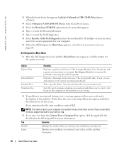
... the test you want . Errors Displays error conditions encountered, error codes, and the problem description. 20 Quick Reference Guide If you contact Dell, technical support will ask for your part. Option Express Test Extended Test Custom Test Symptom Tree Function Performs a quick test of each test...typically takes 10 to 20 minutes and requires no interaction on the screen. Tab Function Results Displays the results of the problem. www.dell.com | support.dell.com 3 When the boot device list appears, highlight Onboard or USB CD-ROM and press . 4 Select Onboard or USB CD...
... the test you want . Errors Displays error conditions encountered, error codes, and the problem description. 20 Quick Reference Guide If you contact Dell, technical support will ask for your part. Option Express Test Extended Test Custom Test Symptom Tree Function Performs a quick test of each test...typically takes 10 to 20 minutes and requires no interaction on the screen. Tab Function Results Displays the results of the problem. www.dell.com | support.dell.com 3 When the boot device list appears, highlight Onboard or USB CD-ROM and press . 4 Select Onboard or USB CD...

Quick Reference Guide
Page 21
Tab Help Configuration Parameters Function Describes the test and may not display the names of the screen. The Dell Diagnostics obtains configuration information for running the Dell Diagnostics from system setup, memory, and various internal tests, and it displays the information in the device list in the... Utilities CD, remove the CD. 5 Close the test screen to return to your hardware configuration for the selected device. To exit the Dell Diagnostics and restart the computer, close the Main Menu screen. Allows you to customize the test by changing the test settings. 4 When ...
Tab Help Configuration Parameters Function Describes the test and may not display the names of the screen. The Dell Diagnostics obtains configuration information for running the Dell Diagnostics from system setup, memory, and various internal tests, and it displays the information in the device list in the... Utilities CD, remove the CD. 5 Close the test screen to return to your hardware configuration for the selected device. To exit the Dell Diagnostics and restart the computer, close the Main Menu screen. Allows you to customize the test by changing the test settings. 4 When ...

Quick Reference Guide
Page 22
... light may Check "Diagnostic Lights" on the power supply should turn green. Reattach the DC cable to the power supply. www.dell.com | support.dell.com Power Supply Light Light State Off Yellow Green PSU State Description Troubleshooting No AC, or a fault condition occurred AC present/no...supply is receiving power from the computer for technical assistance. 22 Quick Reference Guide Ensure that the power supply is not identified, contact Dell for at the power supply. Verify that the power supply is engaged. Check the power button light and see if the be faulty...
... light may Check "Diagnostic Lights" on the power supply should turn green. Reattach the DC cable to the power supply. www.dell.com | support.dell.com Power Supply Light Light State Off Yellow Green PSU State Description Troubleshooting No AC, or a fault condition occurred AC present/no...supply is receiving power from the computer for technical assistance. 22 Quick Reference Guide Ensure that the power supply is not identified, contact Dell for at the power supply. Verify that the power supply is engaged. Check the power button light and see if the be faulty...
