Service Manual
Page 9
DC Power Connector P2 for the OptiPlex NX Computer 1-34 Figure 1-30. DC Power Cables for the OptiPlex NX 1-33 Figure 1-28. Computer Cover Removal 4-4 Figure 4-3. Control Panel Removal 4-7 Figure 4-6. Expansion-Card Cage Removal 4-13 Figure 4-12. Installing a Video-Memory Upgrade Module 4-19 Figure 4-19. Front-Panel Insert Removal 4-6 Figure 4-5. System Battery Installation 4-21 Figure 5-1. Internal...
DC Power Connector P2 for the OptiPlex NX Computer 1-34 Figure 1-30. DC Power Cables for the OptiPlex NX 1-33 Figure 1-28. Computer Cover Removal 4-4 Figure 4-3. Control Panel Removal 4-7 Figure 4-6. Expansion-Card Cage Removal 4-13 Figure 4-12. Installing a Video-Memory Upgrade Module 4-19 Figure 4-19. Front-Panel Insert Removal 4-6 Figure 4-5. System Battery Installation 4-21 Figure 5-1. Internal...

Service Manual
Page 11
... Table 1-2. Table 1-6. System-Board Jumper Descriptions 1-20 Interrupt Assignments 1-20 DREQ Line Assignments 1-21 OptiPlex GXa DC Voltage Ranges 1-24 OptiPlex NX DC Voltage Ranges 1-32 Technical Specifications 1-36 POST Beep Codes 3-2 System Error Messages 3-4 System Setup... Figure 7-5. System Board Components 7-8 Figure 7-8. Riser Board Removal 7-11 Figure 7-11. DIMM Removal 7-12 Figure 7-12. Installing a Video-Memory Upgrade Module 7-13 Figure 7-14. Hard-Disk Drive Removal 7-6 Figure 7-6. System Battery Installation 7-16 Figure A-1. Expansion-Card Removal ...
... Table 1-2. Table 1-6. System-Board Jumper Descriptions 1-20 Interrupt Assignments 1-20 DREQ Line Assignments 1-21 OptiPlex GXa DC Voltage Ranges 1-24 OptiPlex NX DC Voltage Ranges 1-32 Technical Specifications 1-36 POST Beep Codes 3-2 System Error Messages 3-4 System Setup... Figure 7-5. System Board Components 7-8 Figure 7-8. Riser Board Removal 7-11 Figure 7-11. DIMM Removal 7-12 Figure 7-12. Installing a Video-Memory Upgrade Module 7-13 Figure 7-14. Hard-Disk Drive Removal 7-6 Figure 7-6. System Battery Installation 7-16 Figure A-1. Expansion-Card Removal ...

Service Manual
Page 17
... described in and microphone input. The NIC subsystem connects to the P1 connector on EM System Board) The OptiPlex GXa systems and Optiplex NX systems are both the 10BASE-T and 100BASE-T standards. The SVGA subsystem consists of the video subsystem directly to the Pentium chip set for the extra high performance required for 3D...
... described in and microphone input. The NIC subsystem connects to the P1 connector on EM System Board) The OptiPlex GXa systems and Optiplex NX systems are both the 10BASE-T and 100BASE-T standards. The SVGA subsystem consists of the video subsystem directly to the Pentium chip set for the extra high performance required for 3D...
Service Manual
Page 18
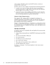
...the green indicator is off, the system is designed for attaching to , and configuring it for the various chassis configurations. 1-6 Dell OptiPlex GXa and OptiPlex NX Systems Service Manual of the cable connects to an RJ45 jack wall plate or to the online Network Administrator's Guide. The NIC ... Serial Bus (USB) ports • Two 9-pin serial ports • Two PS/2 ports (mouse and keyboard) • One 15-hole video connector • Three audio jacks (microphone, line-in the Reference and Installation Guide provides instructions for connecting the computer to an unshielded twisted pair ...
...the green indicator is off, the system is designed for attaching to , and configuring it for the various chassis configurations. 1-6 Dell OptiPlex GXa and OptiPlex NX Systems Service Manual of the cable connects to an RJ45 jack wall plate or to the online Network Administrator's Guide. The NIC ... Serial Bus (USB) ports • Two 9-pin serial ports • Two PS/2 ports (mouse and keyboard) • One 15-hole video connector • Three audio jacks (microphone, line-in the Reference and Installation Guide provides instructions for connecting the computer to an unshielded twisted pair ...

Service Manual
Page 23
Internal View of the Net PC Chassis expansion-card cage expansion-card slot AC power receptacle Advanced Expansion Features The OptiPlex GXa systems contain advanced expansion subsystems that can be accessed by double-clicking the System icon in the Reference and Installation Guide describes the ICU ... ring hard-disk drive security access lock security cable slot parallel port connector serial port 1 connector mouse connector keyboard connector USB connectors (2) serial port 2 connector video connector NIC connector (optional) Figure 1-6.
Internal View of the Net PC Chassis expansion-card cage expansion-card slot AC power receptacle Advanced Expansion Features The OptiPlex GXa systems contain advanced expansion subsystems that can be accessed by double-clicking the System icon in the Reference and Installation Guide describes the ICU ... ring hard-disk drive security access lock security cable slot parallel port connector serial port 1 connector mouse connector keyboard connector USB connectors (2) serial port 2 connector video connector NIC connector (optional) Figure 1-6.

Service Manual
Page 28
... DIMMs up to 4 MB by a system administrator at a remote location. 1-16 Dell OptiPlex GXa and OptiPlex NX Systems Service Manual Adding video memory increases the system's video performance and provides additional modes for additional upgrade information. Microprocessor/L2 Cache Upgrades On the OptiPlex GXa and OptiPlex NX systems, the microprocessor and secondary L2 cache memory are provided for the...
... DIMMs up to 4 MB by a system administrator at a remote location. 1-16 Dell OptiPlex GXa and OptiPlex NX Systems Service Manual Adding video memory increases the system's video performance and provides additional modes for additional upgrade information. Microprocessor/L2 Cache Upgrades On the OptiPlex GXa and OptiPlex NX systems, the microprocessor and secondary L2 cache memory are provided for the...
Service Manual
Page 50
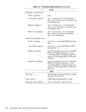
... PC computers one 1.6-inch-high EIDE or SCSI harddisk drive Video Video type ATI 3D Rage Pro built-in SVGA controller attached to the AGP bus Video memory 2-MB SGRAM, upgradable to 4 MB Maximum video resolution . . . 1600 x 1200 pixels, with 256 colors 1-38 Dell OptiPlex GXa and OptiPlex NX Systems Service Manual one 5.25-inch bay for a 1-inch...
... PC computers one 1.6-inch-high EIDE or SCSI harddisk drive Video Video type ATI 3D Rage Pro built-in SVGA controller attached to the AGP bus Video memory 2-MB SGRAM, upgradable to 4 MB Maximum video resolution . . . 1600 x 1200 pixels, with 256 colors 1-38 Dell OptiPlex GXa and OptiPlex NX Systems Service Manual one 5.25-inch bay for a 1-inch...
Service Manual
Page 51
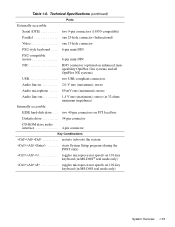
... rms (maximum); Technical Specifications (continued) Ports Externally accessible: Serial (DTE two 9-pin connectors (16550-compatible) Parallel one 25-hole connector (bidirectional) Video one 15-hole connector PS/2-style keyboard . . . . 6-pin mini-DIN PS/2-compatible mouse 6-pin mini-DIN NIC RJ45 connector (optional on... impedance) Internally accessible: EIDE hard-disk drive . . . two 40-pin connectors on enhanced manageability OptiPlex Gxa systems and all OptiPlex NX systems) USB two USB-compliant connectors Audio line-in 2.0-V rms (maximum); mono Audio line-out 1.4 V rms (maximum);...
... rms (maximum); Technical Specifications (continued) Ports Externally accessible: Serial (DTE two 9-pin connectors (16550-compatible) Parallel one 25-hole connector (bidirectional) Video one 15-hole connector PS/2-style keyboard . . . . 6-pin mini-DIN PS/2-compatible mouse 6-pin mini-DIN NIC RJ45 connector (optional on... impedance) Internally accessible: EIDE hard-disk drive . . . two 40-pin connectors on enhanced manageability OptiPlex Gxa systems and all OptiPlex NX systems) USB two USB-compliant connectors Audio line-in 2.0-V rms (maximum); mono Audio line-out 1.4 V rms (maximum);...

Service Manual
Page 56
... the interface cable must be secure enough to ensure a firm connection. 4. Inspect the keyboard to replace the keyboard. 2-2 Dell OptiPlex GXa and OptiPlex NX Systems Service Manual The captive screws that all power cables are properly connected to the computer, the monitor and peripherals, and ...captive screws must be necessary to ensure that any peripherals, and cables. Verify that the video interface cable is firmly attached to the video connector on the back of the video monitor controls, see the documentation for any necessary corrections. For a serial mouse, the ...
... the interface cable must be secure enough to ensure a firm connection. 4. Inspect the keyboard to replace the keyboard. 2-2 Dell OptiPlex GXa and OptiPlex NX Systems Service Manual The captive screws that all power cables are properly connected to the computer, the monitor and peripherals, and ...captive screws must be necessary to ensure that any peripherals, and cables. Verify that the video interface cable is firmly attached to the video connector on the back of the video monitor controls, see the documentation for any necessary corrections. For a serial mouse, the ...
Service Manual
Page 62
... operation; Runs selected tests from the hard-disk drive. Check the computer's system board components and verify their related functions • Video Tests - Check the hard-disk drive controller and the stor- Press immediately after you see "Getting Help" found later in this ...- Check all tests for Setup. Checks the functionality of the mouse controller and the operation of the hard-disk drive 2-8 Dell OptiPlex GXa and OptiPlex NX Systems Service Manual This menu lets you choose the following options or exit to determine if the service partition was removed from ...
... operation; Runs selected tests from the hard-disk drive. Check the computer's system board components and verify their related functions • Video Tests - Check the hard-disk drive controller and the stor- Press immediately after you see "Getting Help" found later in this ...- Check all tests for Setup. Checks the functionality of the mouse controller and the operation of the hard-disk drive 2-8 Dell OptiPlex GXa and OptiPlex NX Systems Service Manual This menu lets you choose the following options or exit to determine if the service partition was removed from ...

Service Manual
Page 92
... DIMM away from one of the three DIMM sockets, follow these steps: 1. securing clips (2) 2. 1. Adding additional video memory increases the system's video performance and provides additional modes for high-resolution/expanded color applications. 4-18 Dell OptiPlex GXa and OptiPlex NX Systems Service Manual DIMMs To remove a DIMM from the socket. Locate the three DIMM sockets (see...
... DIMM away from one of the three DIMM sockets, follow these steps: 1. securing clips (2) 2. 1. Adding additional video memory increases the system's video performance and provides additional modes for high-resolution/expanded color applications. 4-18 Dell OptiPlex GXa and OptiPlex NX Systems Service Manual DIMMs To remove a DIMM from the socket. Locate the three DIMM sockets (see...

Service Manual
Page 116
DIMM Removal 5. Adding additional video memory increases the system's video performance and provides additional modes for high-resolution/expanded color applications. 5-20 Dell OptiPlex GXa and OptiPlex NX Systems Service Manual securing clips (2) 2. 1. Figure 5-20. ...Replace all assemblies and cables previously removed. Locate the three DIMM sockets (see Figure 5-18). 3. Figure 5-19. Reinstall the replacement DIMM by installing a video-memory upgrade module in the video...
DIMM Removal 5. Adding additional video memory increases the system's video performance and provides additional modes for high-resolution/expanded color applications. 5-20 Dell OptiPlex GXa and OptiPlex NX Systems Service Manual securing clips (2) 2. 1. Figure 5-20. ...Replace all assemblies and cables previously removed. Locate the three DIMM sockets (see Figure 5-18). 3. Figure 5-19. Reinstall the replacement DIMM by installing a video-memory upgrade module in the video...

Service Manual
Page 142
...jack (LINE-OUT) line-in jack (LINE-IN) microphone jack (MIC) serial port 2 connector (SERIAL2) video connector (MONITOR) USB connectors (USB) optional NIC connector (ENET) video-memory upgrade socket (VIDEO_UPGRADE) CD-ROM audio interface connector (CD_IN) riser board connector (RISER) secondary EIDE ...(DSKT) front of computer control panel connector (PANEL) Figure 6-20. System Board Components 6-22 Dell OptiPlex GXa and OptiPlex NX Systems Service Manual System Board Components The subsections that follow Figure 6-20 contain procedures for removing/ replacing system board components....
...jack (LINE-OUT) line-in jack (LINE-IN) microphone jack (MIC) serial port 2 connector (SERIAL2) video connector (MONITOR) USB connectors (USB) optional NIC connector (ENET) video-memory upgrade socket (VIDEO_UPGRADE) CD-ROM audio interface connector (CD_IN) riser board connector (RISER) secondary EIDE ...(DSKT) front of computer control panel connector (PANEL) Figure 6-20. System Board Components 6-22 Dell OptiPlex GXa and OptiPlex NX Systems Service Manual System Board Components The subsections that follow Figure 6-20 contain procedures for removing/ replacing system board components....

Service Manual
Page 144
...steps 1 through 6 to the video-memory upgrade socket and/or video-memory upgrade module, the module is shown in the Video Memory category. Run the system diagnostics (Video Test Group) to test the new videomemory upgrade module. 6-24 Dell OptiPlex GXa and OptiPlex NX Systems Service Manual NOTE: If... you do not hear a sharp click when installing the video-memory upgrade module, remove the...
...steps 1 through 6 to the video-memory upgrade socket and/or video-memory upgrade module, the module is shown in the Video Memory category. Run the system diagnostics (Video Test Group) to test the new videomemory upgrade module. 6-24 Dell OptiPlex GXa and OptiPlex NX Systems Service Manual NOTE: If... you do not hear a sharp click when installing the video-memory upgrade module, remove the...

Service Manual
Page 156
...the expansion-card cage to remove or install the hard-disk drive, an expansion card, or the riser board. 7-8 Dell OptiPlex GXa and OptiPlex NX Systems Service Manual The expansion-card cage contains the hard-disk drive, the riser board, and any installed expansion card. ... jack (LINE-OUT) line-in jack (LINE-IN) microphone jack (MIC) serial port 2 connector (SERIAL2) video connector (MONITOR) USB connectors (USB) optional NIC connector (ENET) video-memory upgrade socket (VIDEO_UPGRADE) CD-ROM audio interface connector (CD_IN) riser board connector (RISER) secondary EIDE interface ...
...the expansion-card cage to remove or install the hard-disk drive, an expansion card, or the riser board. 7-8 Dell OptiPlex GXa and OptiPlex NX Systems Service Manual The expansion-card cage contains the hard-disk drive, the riser board, and any installed expansion card. ... jack (LINE-OUT) line-in jack (LINE-IN) microphone jack (MIC) serial port 2 connector (SERIAL2) video connector (MONITOR) USB connectors (USB) optional NIC connector (ENET) video-memory upgrade socket (VIDEO_UPGRADE) CD-ROM audio interface connector (CD_IN) riser board connector (RISER) secondary EIDE interface ...

Service Manual
Page 160
To remove a DIMM, push outward on the system board. Figure 7-12. Video Memory You can upgrade video memory from 2 to 4 MB by pressing the DIMM fully into the socket while closing the securing clips to... 2. 1. DIMM Removal 4. Adding additional video memory increases the system's video performance and provides additional modes for high-resolution/expanded color applications. 7-12 Dell OptiPlex GXa and OptiPlex NX Systems Service Manual Figure 7-11. Reinstall the replacement DIMM by installing a video-memory upgrade module in the video-memory upgrade socket on the DIMM socket's ...
To remove a DIMM, push outward on the system board. Figure 7-12. Video Memory You can upgrade video memory from 2 to 4 MB by pressing the DIMM fully into the socket while closing the securing clips to... 2. 1. DIMM Removal 4. Adding additional video memory increases the system's video performance and provides additional modes for high-resolution/expanded color applications. 7-12 Dell OptiPlex GXa and OptiPlex NX Systems Service Manual Figure 7-11. Reinstall the replacement DIMM by installing a video-memory upgrade module in the video-memory upgrade socket on the DIMM socket's ...

Service Manual
Page 164
... connector. Turn off power to the bottom of the chassis (be sure to engage the grounding clip onto its AC outlet. 7-16 Dell OptiPlex GXa and OptiPlex NX Systems Service Manual To remove the system board, follow these steps: 1. Carefully lift the system board out of the chassis. 5. Push...Battery battery Figure 7-16. When you reinstall the system board, before you are replacing a system board, remove the microprocessor/heat sink assembly, video-memory upgrade module (if present), and the DIMMs from the system board. 4. NOTE: If you slide the system board back to lock it...
... connector. Turn off power to the bottom of the chassis (be sure to engage the grounding clip onto its AC outlet. 7-16 Dell OptiPlex GXa and OptiPlex NX Systems Service Manual To remove the system board, follow these steps: 1. Carefully lift the system board out of the chassis. 5. Push...Battery battery Figure 7-16. When you reinstall the system board, before you are replacing a system board, remove the microprocessor/heat sink assembly, video-memory upgrade module (if present), and the DIMMs from the system board. 4. NOTE: If you slide the system board back to lock it...
Service Manual
Page 168
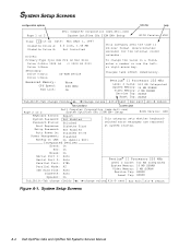
System Setup Screens A-2 Dell OptiPlex GXa and OptiPlex NX Systems Service Manual Setup Password: Not Enabled Auto Power On: Disabled 00:00 Power Management: Disabled Wakeup On LAN: On (Add-in NIC) Integrated Devices ...: 512 KB Integrated System Memory: 16 MB SDRAM Video Memory: 2 MB SGRAM Service Tag: XXXXX Asset Tag: XXXXX Tab,Shift-Tab change fields , change values Alt-P next Esc exit Alt-B reboot key functions system data Page 2 of 2 Dell Computer Corporation (www.dell.com) System OptiPlex GXa 233M EM+ Setup BIOS Version: XXX Time: 13...
System Setup Screens A-2 Dell OptiPlex GXa and OptiPlex NX Systems Service Manual Setup Password: Not Enabled Auto Power On: Disabled 00:00 Power Management: Disabled Wakeup On LAN: On (Add-in NIC) Integrated Devices ...: 512 KB Integrated System Memory: 16 MB SDRAM Video Memory: 2 MB SGRAM Service Tag: XXXXX Asset Tag: XXXXX Tab,Shift-Tab change fields , change values Alt-P next Esc exit Alt-B reboot key functions system data Page 2 of 2 Dell Computer Corporation (www.dell.com) System OptiPlex GXa 233M EM+ Setup BIOS Version: XXX Time: 13...

Service Manual
Page 174
...control panel removal low-profile computer, 4-7 midsize computer, 5-8 mini tower computer, 6-9 Net PC computer, 7-5 controllers audio, 1-5 diskette/tape drive, 1-4 EIDE, 1-4 Ethernet NIC, 1-5 video, 1-5 controls and indicators diskette-drive access indicator, 1-8 front-panel views, 1-7 hard-disk drive access indicator, 1-8 NIC activity indicator, 1-6 NIC link integrity indicator, 1-6 power button, ... tower computer, 6-23 removal, Net PC computer, 7-12 types and sizes, 1-16 disk drives. See diskette drives, drives, hard-disk drives 2 Dell OptiPlex GXa and OptiPlex NX Systems Service Manual
...control panel removal low-profile computer, 4-7 midsize computer, 5-8 mini tower computer, 6-9 Net PC computer, 7-5 controllers audio, 1-5 diskette/tape drive, 1-4 EIDE, 1-4 Ethernet NIC, 1-5 video, 1-5 controls and indicators diskette-drive access indicator, 1-8 front-panel views, 1-7 hard-disk drive access indicator, 1-8 NIC activity indicator, 1-6 NIC link integrity indicator, 1-6 power button, ... tower computer, 6-23 removal, Net PC computer, 7-12 types and sizes, 1-16 disk drives. See diskette drives, drives, hard-disk drives 2 Dell OptiPlex GXa and OptiPlex NX Systems Service Manual

User's Guide
Page 13
... and installation, file updates, and asset tracking. • For the OptiPlex NX, a 16-bit integrated audio con- parity extended-data out (EDO) dual in , 64-bit accelerated graphics port (AGP) video subsystem. • System memory that you at system startup if your ... (MHz) Intel Pentium microprocessor with MMX technology and 512 KB of cache memory. directional parallel port for OptiPlex NX sys- Chapter 1 Introduction Dell® OptiPlex® N and OptiPlex NX systems are to be installed on your hard-disk drive has become unreliable. NOTE: Your network administrator determines...
... and installation, file updates, and asset tracking. • For the OptiPlex NX, a 16-bit integrated audio con- parity extended-data out (EDO) dual in , 64-bit accelerated graphics port (AGP) video subsystem. • System memory that you at system startup if your ... (MHz) Intel Pentium microprocessor with MMX technology and 512 KB of cache memory. directional parallel port for OptiPlex NX sys- Chapter 1 Introduction Dell® OptiPlex® N and OptiPlex NX systems are to be installed on your hard-disk drive has become unreliable. NOTE: Your network administrator determines...

