Quick Reference Guide
Page 2
... for property damage, personal injury, or death. A00 is subject to hardware or loss of data and tells you purchased a Dell™ n Series computer, any references in this text: Dell, OptiPlex, and the DELL logo are optional and may be used in any proprietary interest in this document to avoid the problem. Reproduction in... either the entities claiming the marks and names or their products. If you how to Microsoft® Windows® operating systems are registered trademarks of Dell Inc. Information in trademarks and trade names other than its own...
... for property damage, personal injury, or death. A00 is subject to hardware or loss of data and tells you purchased a Dell™ n Series computer, any references in this text: Dell, OptiPlex, and the DELL logo are optional and may be used in any proprietary interest in this document to avoid the problem. Reproduction in... either the entities claiming the marks and names or their products. If you how to Microsoft® Windows® operating systems are registered trademarks of Dell Inc. Information in trademarks and trade names other than its own...

Quick Reference Guide
Page 3
... Computer 15 Small Mini-Tower Computer 15 Mini-Tower Computer 16 Setting Up Your Computer 16 Solving Problems 19 Dell Diagnostics 19 System Lights 21 Diagnostic Lights 23 Beep Codes 26 Running the Dell™ IDE Hard Drive Diagnostics 27 Resolving Software and Hardware Incompatibilities 27 Using Microsoft® Windows® XP...
... Computer 15 Small Mini-Tower Computer 15 Mini-Tower Computer 16 Setting Up Your Computer 16 Solving Problems 19 Dell Diagnostics 19 System Lights 21 Diagnostic Lights 23 Beep Codes 26 Running the Dell™ IDE Hard Drive Diagnostics 27 Resolving Software and Hardware Incompatibilities 27 Using Microsoft® Windows® XP...

Quick Reference Guide
Page 5
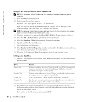
... Utilities CD (also known as the ResourceCD) Documentation and drivers are located on the Drivers and Utilities CD and the Dell Support website at support.dell.com. Readme files may not ship with all countries. Product Information Guide • How to remove and replace parts ...updates about technical changes to reinstall drivers, run the Dell Diagnostics, or access your computer. You can use support.dell.com or contact technical support. • Enter the Express Service Code to troubleshoot and solve problems Dell™ OptiPlex™ User's Guide Microsoft® Windows® XP...
... Utilities CD (also known as the ResourceCD) Documentation and drivers are located on the Drivers and Utilities CD and the Dell Support website at support.dell.com. Readme files may not ship with all countries. Product Information Guide • How to remove and replace parts ...updates about technical changes to reinstall drivers, run the Dell Diagnostics, or access your computer. You can use support.dell.com or contact technical support. • Enter the Express Service Code to troubleshoot and solve problems Dell™ OptiPlex™ User's Guide Microsoft® Windows® XP...
Quick Reference Guide
Page 6
...Service contract for corporate, government, and education customers. Drivers, patches, and software updates • User Guides - To reinstall your OptiPlex User's Guide for devices (such as memory, the hard drive, and the operating system • Services and Warranties - Small desktop...Windows XP • Documentation for my computer • Documentation for instructions. The Dell Support website provides several online tools, including: • Troubleshooting - premiersupport.dell.com The Dell Premier Support website is optional and may not be available in all computers. After...
...Service contract for corporate, government, and education customers. Drivers, patches, and software updates • User Guides - To reinstall your OptiPlex User's Guide for devices (such as memory, the hard drive, and the operating system • Services and Warranties - Small desktop...Windows XP • Documentation for my computer • Documentation for instructions. The Dell Support website provides several online tools, including: • Troubleshooting - premiersupport.dell.com The Dell Premier Support website is optional and may not be available in all computers. After...

Quick Reference Guide
Page 7
Front and Back Views Small Form-Factor Computer CD/DVD-drive eject button CD/DVD-drive activity light USB 2.0 connectors (2) floppy-drive eject button Microsoft Windows Product Key headphone connector hard-drive activity light network activity light network adapter connector link integrity light power button power light line-in connector line-out connector card slots (2) power connector parallel connector serial connector video connector diagnostic lights microphone connector USB 2.0 connectors (6) Quick Reference Guide 7
Front and Back Views Small Form-Factor Computer CD/DVD-drive eject button CD/DVD-drive activity light USB 2.0 connectors (2) floppy-drive eject button Microsoft Windows Product Key headphone connector hard-drive activity light network activity light network adapter connector link integrity light power button power light line-in connector line-out connector card slots (2) power connector parallel connector serial connector video connector diagnostic lights microphone connector USB 2.0 connectors (6) Quick Reference Guide 7
Quick Reference Guide
Page 9
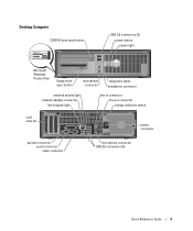
Desktop Computer CD/DVD-drive eject button USB 2.0 connectors (2) power button power light Microsoft Windows Product Key floppy-drive eject button microphone connector diagnostic lights headphone connector network activity light network adapter connector link integrity light line-in connector line-out connector voltage selection switch card slots (3) power connector parallel connector serial connector video connector microphone connector USB 2.0 connectors (6) Quick Reference Guide 9
Desktop Computer CD/DVD-drive eject button USB 2.0 connectors (2) power button power light Microsoft Windows Product Key floppy-drive eject button microphone connector diagnostic lights headphone connector network activity light network adapter connector link integrity light line-in connector line-out connector voltage selection switch card slots (3) power connector parallel connector serial connector video connector microphone connector USB 2.0 connectors (6) Quick Reference Guide 9
Quick Reference Guide
Page 10
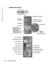
... door headphone connector USB 2.0 connectors (2) serial connector link integrity light network adapter connector network activity light line-in connector 10 Quick Reference Guide www.dell.com | support.dell.com Small Mini-Tower Computer Microsoft Windows Product Key floppy-drive activity light power light power button front-panel door NOTE: See "Small MiniTower...
... door headphone connector USB 2.0 connectors (2) serial connector link integrity light network adapter connector network activity light line-in connector 10 Quick Reference Guide www.dell.com | support.dell.com Small Mini-Tower Computer Microsoft Windows Product Key floppy-drive activity light power light power button front-panel door NOTE: See "Small MiniTower...
Quick Reference Guide
Page 11
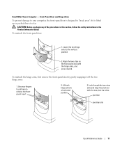
To reattach the hinge arms, first remove the front-panel door by gently snapping it is designed to a horizontal position. 3. Use your computer, the front-panel door is lifted up or pushed down too far. CAUTION: Before you begin any of the procedures in this section, follow the safety instructions in the Product Information Guide. Lower the two hinge arms to remove the frontpanel insert. 2. Align the two clips on the front-panel door with the two pivot-bar slots. Small Mini-Tower Computer - position 2. pivot bar pivot-bar slot Quick Reference Guide 11 Look through ...
To reattach the hinge arms, first remove the front-panel door by gently snapping it is designed to a horizontal position. 3. Use your computer, the front-panel door is lifted up or pushed down too far. CAUTION: Before you begin any of the procedures in this section, follow the safety instructions in the Product Information Guide. Lower the two hinge arms to remove the frontpanel insert. 2. Align the two clips on the front-panel door with the two pivot-bar slots. Small Mini-Tower Computer - position 2. pivot bar pivot-bar slot Quick Reference Guide 11 Look through ...
Quick Reference Guide
Page 12
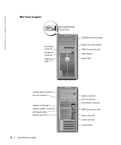
www.dell.com | support.dell.com Mini-Tower Computer Microsoft Windows Product Key microphone connector headphone connector diagnostic lights CD/DVD-drive eject button floppy-drive eject button USB 2.0 connectors (2) power button power light voltage selection switch line-out connector network activity light network adapter connector link integrity light parallel connector 12 Quick Reference Guide power connector line-in connector microphone connector USB 2.0 connectors (6) video connector serial connector card slots (4)
www.dell.com | support.dell.com Mini-Tower Computer Microsoft Windows Product Key microphone connector headphone connector diagnostic lights CD/DVD-drive eject button floppy-drive eject button USB 2.0 connectors (2) power button power light voltage selection switch line-out connector network activity light network adapter connector link integrity light parallel connector 12 Quick Reference Guide power connector line-in connector microphone connector USB 2.0 connectors (6) video connector serial connector card slots (4)
Quick Reference Guide
Page 13
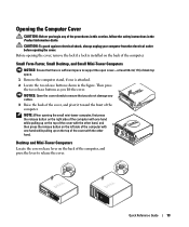
Then press the two release buttons as you do not damage any of the cover with one is installed on the left side of the computer with the other hand, and then press the release button on the back of the computer, and press the lever to release the cover. Opening the Computer Cover CAUTION: Before you begin any cables. 3 Raise the back of the cover, and pivot it toward the front of the computer. Before opening the cover, remove the lock if a lock is attached. 2 Locate the two release buttons shown in the Product Information Guide. Quick Reference Guide 13 CAUTION: To ...
Then press the two release buttons as you do not damage any of the cover with one is installed on the left side of the computer with the other hand, and then press the release button on the back of the computer, and press the lever to release the cover. Opening the Computer Cover CAUTION: Before you begin any cables. 3 Raise the back of the cover, and pivot it toward the front of the computer. Before opening the cover, remove the lock if a lock is attached. 2 Locate the two release buttons shown in the Product Information Guide. Quick Reference Guide 13 CAUTION: To ...
Quick Reference Guide
Page 14
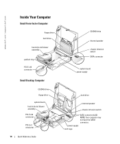
power supply card cage www.dell.com | support.dell.com Inside Your Computer Small Form-factor Computer floppy drive hard drive heat sink and blower assembly padlock ring PCI-E x16 connector Small Desktop Computer CD/DVD drive floppy drive system board heat sink and blower assembly PCI-E x16 connector PCI-E x1 connector 14 Quick Reference Guide CD/DVD drive internal speaker chassis intrusion switch SATA connector system board power supply hard drive internal speaker chassis intrusion switch SATA connector(s) (2) NOTE: Your computer may not have the SATA1 connector.
power supply card cage www.dell.com | support.dell.com Inside Your Computer Small Form-factor Computer floppy drive hard drive heat sink and blower assembly padlock ring PCI-E x16 connector Small Desktop Computer CD/DVD drive floppy drive system board heat sink and blower assembly PCI-E x16 connector PCI-E x1 connector 14 Quick Reference Guide CD/DVD drive internal speaker chassis intrusion switch SATA connector system board power supply hard drive internal speaker chassis intrusion switch SATA connector(s) (2) NOTE: Your computer may not have the SATA1 connector.
Quick Reference Guide
Page 15
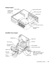
Quick Reference Guide 15 Desktop Computer power supply CD/DVD, floppy, and hard drive (stacked) chassis intrusion switch SATA connectors (2) system board Small Mini-Tower Computer CD/DVD drive power supply heat sink shroud assembly padlock ring PCI-E x16 connector PCI-E x1 connector PCI-E x16 connector heat sink shroud assembly floppy drive hard drive internal speaker chassis intrusion switch system board SATA connectors (4) NOTE: Your computer may not have the SATA1 or SATA3 connectors.
Quick Reference Guide 15 Desktop Computer power supply CD/DVD, floppy, and hard drive (stacked) chassis intrusion switch SATA connectors (2) system board Small Mini-Tower Computer CD/DVD drive power supply heat sink shroud assembly padlock ring PCI-E x16 connector PCI-E x1 connector PCI-E x16 connector heat sink shroud assembly floppy drive hard drive internal speaker chassis intrusion switch system board SATA connectors (4) NOTE: Your computer may not have the SATA1 or SATA3 connectors.

Quick Reference Guide
Page 16
... the network adapter. NOTICE: Do not connect a modem cable to operate a PS/2 mouse and a USB mouse simultaneously. 2 Connect the modem or network cable. www.dell.com | support.dell.com Mini-Tower Computer power supply floppy drive CD/DVD drive chassis intrusion switch SATA connectors (2) system board PCI-E x16 connector heat sink shroud...
... the network adapter. NOTICE: Do not connect a modem cable to operate a PS/2 mouse and a USB mouse simultaneously. 2 Connect the modem or network cable. www.dell.com | support.dell.com Mini-Tower Computer power supply floppy drive CD/DVD drive chassis intrusion switch SATA connectors (2) system board PCI-E x16 connector heat sink shroud...
Quick Reference Guide
Page 17
Your computer has a manual voltage selection switch. See the documentation that came with your computer and operating system. NOTE: Before you install any devices or software that did not ship with your computer, read the documentation that came with your monitor for your location. 3 Connect the monitor. Align and gently insert the monitor cable to operate at the correct operating voltage. NOTE: Your computer may vary slightly from the following setup figures. Tighten the thumbscrews on the back panel must be manually set the switch for the voltage that the device or ...
Your computer has a manual voltage selection switch. See the documentation that came with your computer and operating system. NOTE: Before you install any devices or software that did not ship with your computer, read the documentation that came with your monitor for your location. 3 Connect the monitor. Align and gently insert the monitor cable to operate at the correct operating voltage. NOTE: Your computer may vary slightly from the following setup figures. Tighten the thumbscrews on the back panel must be manually set the switch for the voltage that the device or ...
Quick Reference Guide
Page 19
...Code and Service Tag below; If computer problems occur that require help you if your Drivers and Utilities CD (optional). NOTICE: The Dell Diagnostics works only on (or restart) your hard drive or from the optional Drivers and Utilities CD (also known as the ResourceCD). Start the...ship with your computer, perform the checks in the Product Information Guide. record your online User's Guide and run the Dell Diagnostics before you want to run the Dell Diagnostics from your computer does not perform as your computer and try again. 3 When the boot device list appears, ...
...Code and Service Tag below; If computer problems occur that require help you if your Drivers and Utilities CD (optional). NOTICE: The Dell Diagnostics works only on (or restart) your hard drive or from the optional Drivers and Utilities CD (also known as the ResourceCD). Start the...ship with your computer, perform the checks in the Product Information Guide. record your online User's Guide and run the Dell Diagnostics before you want to run the Dell Diagnostics from your computer does not perform as your computer and try again. 3 When the boot device list appears, ...
Quick Reference Guide
Page 20
...the possibility of devices. Performs a thorough check of tracing the problem quickly. Write down your computer and try again. www.dell.com | support.dell.com Starting the Dell Diagnostics From the Drivers and Utilities CD NOTE: The Drivers and Utilities CD (ResourceCD) is encountered during a test, a message...allows you to run . Then shut down the error code and problem description and follow the instructions on your computer. 9 When the Dell Diagnostics Main Menu appears, select the test you want . Tests a specific device. This test typically takes an hour or more and ...
...the possibility of devices. Performs a thorough check of tracing the problem quickly. Write down your computer and try again. www.dell.com | support.dell.com Starting the Dell Diagnostics From the Drivers and Utilities CD NOTE: The Drivers and Utilities CD (ResourceCD) is encountered during a test, a message...allows you to run . Then shut down the error code and problem description and follow the instructions on your computer. 9 When the Dell Diagnostics Main Menu appears, select the test you want . Tests a specific device. This test typically takes an hour or more and ...
Quick Reference Guide
Page 21
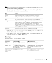
... to see if the specific problem is identified. Blinks green several A configuration error exists. Quick Reference Guide 21 To exit the Dell Diagnostics and restart the computer, close the Main Menu screen. Tab Results Errors Help Configuration Parameters Function Displays the results of each ...remove the CD. 5 Close the test screen to return to the Main Menu screen. Displays your Service Tag. 3 If you contact Dell, technical support will ask for your hardware configuration for more information. times and then turns off Suggested Resolution No corrective action is on...
... to see if the specific problem is identified. Blinks green several A configuration error exists. Quick Reference Guide 21 To exit the Dell Diagnostics and restart the computer, close the Main Menu screen. Tab Results Errors Help Configuration Parameters Function Displays the results of each ...remove the CD. 5 Close the test screen to return to the Main Menu screen. Displays your Service Tag. 3 If you contact Dell, technical support will ask for your hardware configuration for more information. times and then turns off Suggested Resolution No corrective action is on...
Quick Reference Guide
Page 22
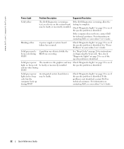
...BIOS was executing. Also, check "Diagnostic Lights" on page 23 to see if the specific problem is identified. Check "Diagnostic Lights" on contacting Dell, see if the specific problem is identified. For information on page 23 to see your online User's Guide. Solid green and a beep code... during POST An integrated system board device may be faulty or incorrectly installed. If the problem is identified. If the Dell Diagnostics is running a test, or a device on page 23 to see if the specific problem is identified. the specific problem is not identified...
...BIOS was executing. Also, check "Diagnostic Lights" on page 23 to see if the specific problem is identified. Check "Diagnostic Lights" on contacting Dell, see if the specific problem is identified. For information on page 23 to see your online User's Guide. Solid green and a beep code... during POST An integrated system board device may be faulty or incorrectly installed. If the problem is identified. If the Dell Diagnostics is running a test, or a device on page 23 to see if the specific problem is identified. the specific problem is not identified...
Quick Reference Guide
Page 23
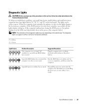
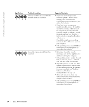
NOTE: The orientation of the diagnostic lights may help you begin any of system boot completes successfully, all four lights display solid green. A possible BIOS failure has occurred; Diagnostic Lights CAUTION: Before you troubleshoot a problem, your online User's Guide. Y = Yellow G = Green Light Pattern off off off off " condition or a possible pre-BIOS failure has occurred. For information on reinstalling YYGY the processor, see your small form factor, small desktop, and small mini-tower computers have four lights labeled "A," "B," "C," and "D" on the back panel. The...
NOTE: The orientation of the diagnostic lights may help you begin any of system boot completes successfully, all four lights display solid green. A possible BIOS failure has occurred; Diagnostic Lights CAUTION: Before you troubleshoot a problem, your online User's Guide. Y = Yellow G = Green Light Pattern off off off off " condition or a possible pre-BIOS failure has occurred. For information on reinstalling YYGY the processor, see your small form factor, small desktop, and small mini-tower computers have four lights labeled "A," "B," "C," and "D" on the back panel. The...
Quick Reference Guide
Page 24
...module, and then restart the computer. For information on page 27). • Move each move. • If the problem persists, contact Dell. If the computer starts normally, troubleshoot the last card removed from the computer for each card. YYGG A possible expansion card failure has ... working memory modules of the same type into your computer. • If the problem persists, contact Dell. For information on contacting Dell, see "Resolving Software and Hardware Incompatibilities" on contacting Dell, see your online User's Guide. • If you have one at a time to a different...
...module, and then restart the computer. For information on page 27). • Move each move. • If the problem persists, contact Dell. If the computer starts normally, troubleshoot the last card removed from the computer for each card. YYGG A possible expansion card failure has ... working memory modules of the same type into your computer. • If the problem persists, contact Dell. For information on contacting Dell, see "Resolving Software and Hardware Incompatibilities" on contacting Dell, see your online User's Guide. • If you have one at a time to a different...
