

Tower Quick Start Guide- Windows 7
Page 2
... type Computer model Dell.com/support Dell.com/support/manuals Dell.com/support/windows Dell.com/contactdell Features Dell.com/regulatory_compliance D18M D18M003 OptiPlex 7050 Tower OptiPlex 7050 Tower 系列 OptiPlex 7050 Tower (D18M 100 - 240 50 - 60 4 218 號 20 00801-861-011 © 2016 Dell Inc. © 2016 Microsoft Corporation. © 2016 Canonical Ltd. VGA 24. Power connector port 20. Power supply diagnostic light 21...
... type Computer model Dell.com/support Dell.com/support/manuals Dell.com/support/windows Dell.com/contactdell Features Dell.com/regulatory_compliance D18M D18M003 OptiPlex 7050 Tower OptiPlex 7050 Tower 系列 OptiPlex 7050 Tower (D18M 100 - 240 50 - 60 4 218 號 20 00801-861-011 © 2016 Dell Inc. © 2016 Microsoft Corporation. © 2016 Canonical Ltd. VGA 24. Power connector port 20. Power supply diagnostic light 21...
Tower Quick Start Guide- Windows 10
Page 2
...;Smart Power On 18 19 20 21 22 23. USB 3.0 Type-C 포트 7 8 9. USB 2.0 port with PowerShare 5. USB 3.0 端口 6. USB 2.0 端口 15. USB 3.0 連接埠 6. HDMI 포트 10 11. PS/2 16. Product support and manuals Contact Dell 与 Dell Dell Dell Regulatory and safety Regulatory model Regulatory type Computer model OptiPlex 7050 Tower (D18M...
...;Smart Power On 18 19 20 21 22 23. USB 3.0 Type-C 포트 7 8 9. USB 2.0 port with PowerShare 5. USB 3.0 端口 6. USB 2.0 端口 15. USB 3.0 連接埠 6. HDMI 포트 10 11. PS/2 16. Product support and manuals Contact Dell 与 Dell Dell Dell Regulatory and safety Regulatory model Regulatory type Computer model OptiPlex 7050 Tower (D18M...

Owners Manual
Page 2
......24 Memory module...25 Removing memory module...25 Installing memory module...25 Expansion card...26 Removing PCIe expansion card...26 Installing PCIe expansion card...27 Power supply unit...28 Removing power supply unit or PSU...28 2 Contents
......24 Memory module...25 Removing memory module...25 Installing memory module...25 Expansion card...26 Removing PCIe expansion card...26 Installing PCIe expansion card...27 Power supply unit...28 Removing power supply unit or PSU...28 2 Contents

Owners Manual
Page 3
Installing power supply unit or PSU...29 VGA daughter board...30 Removing VGA daughter board...30 Installing VGA daughter board...30 Intrusion switch...32 Removing intrusion switch...32 Installing intrusion switch...33 Power switch...34 Removing power switch...34 Installing power switch...35 Speaker...35 Removing speaker...35 Installing speaker...37 Coin cell battery...37 Removing...
Installing power supply unit or PSU...29 VGA daughter board...30 Removing VGA daughter board...30 Installing VGA daughter board...30 Intrusion switch...32 Removing intrusion switch...32 Installing intrusion switch...33 Power switch...34 Removing power switch...34 Installing power switch...35 Speaker...35 Removing speaker...35 Installing speaker...37 Coin cell battery...37 Removing...

Owners Manual
Page 4
... and Bluetooth drivers...72 Downloading the Wi-Fi driver...72 Realtek HD audio drivers...73 Downloading the audio driver...73 Chapter 7: Troubleshooting your computer 74 Power-Supply Unit Built-in Self-Test ...74 Dell SupportAssist Pre-boot System Performance Check diagnostics 74 Running the SupportAssist Pre-Boot System Performance Check 74 Diagnostic and...
... and Bluetooth drivers...72 Downloading the Wi-Fi driver...72 Realtek HD audio drivers...73 Downloading the audio driver...73 Chapter 7: Troubleshooting your computer 74 Power-Supply Unit Built-in Self-Test ...74 Dell SupportAssist Pre-boot System Performance Check diagnostics 74 Running the SupportAssist Pre-Boot System Performance Check 74 Diagnostic and...

Owners Manual
Page 28
... the connectors on the system board [1] [2]. Disconnect the PSU cables from the computer [2]. 28 Disassembly and reassembly Unroute the PSU cables from the retention clip [4]. Power supply unit Removing power supply unit or PSU Steps 1. cover b.
... the connectors on the system board [1] [2]. Disconnect the PSU cables from the computer [2]. 28 Disassembly and reassembly Unroute the PSU cables from the retention clip [4]. Power supply unit Removing power supply unit or PSU Steps 1. cover b.

Owners Manual
Page 29
Close the front panel door. 6. Connect the PSU cables to the computer. 3. bezel b. Follow the procedure in After working inside your computer. cover 7. Install the: a. Tighten the screws to secure the PSU to the connectors on the system board. 5. Insert the PSU into the PSU slot and slide it towards the back of the cables with the release clips. 4. Route the PSU cables through the retention clips and secure one of the computer until it clicks into place. 2. Disassembly and reassembly 29 Installing power supply unit or PSU Steps 1.
Close the front panel door. 6. Connect the PSU cables to the computer. 3. bezel b. Follow the procedure in After working inside your computer. cover 7. Install the: a. Tighten the screws to secure the PSU to the connectors on the system board. 5. Insert the PSU into the PSU slot and slide it towards the back of the cables with the release clips. 4. Route the PSU cables through the retention clips and secure one of the computer until it clicks into place. 2. Disassembly and reassembly 29 Installing power supply unit or PSU Steps 1.

Owners Manual
Page 64
...of the system fan. This option is disabled by default. Table 15. Allows you to the system in S4 and S5 by default. Power Management Option AC Recovery Auto On Time Deep Sleep Control Fan Control Override USB Wake Support Wake on by default. This option is Disabled ... the processor. Allows you to enable or disable the Intel TurboBoost mode of Intel Ready Mode Technology. This option is reapplied after a power loss. Change the startup time by special LAN signals. ● LAN with PXE Boot - Allows the system to AC power supply. ● Disabled -
...of the system fan. This option is disabled by default. Table 15. Allows you to the system in S4 and S5 by default. Power Management Option AC Recovery Auto On Time Deep Sleep Control Fan Control Override USB Wake Support Wake on by default. This option is Disabled ... the processor. Allows you to enable or disable the Intel TurboBoost mode of Intel Ready Mode Technology. This option is reapplied after a power loss. Change the startup time by special LAN signals. ● LAN with PXE Boot - Allows the system to AC power supply. ● Disabled -
Owners Manual
Page 74
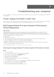
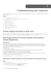
...search in Self-Test (BIST) helps determine if the power-supply unit is working. If there are any issues, error codes are listed. 6. Running the SupportAssist Pre-Boot System Performance Check Steps 1. Click the arrow at www.dell.com/support. 7 Troubleshooting your computer You can troubleshoot your...computer. For more information, see https://www.dell.com/support/kbdoc/000180971. Turn on a specific device, press Esc and click Yes to the page listing. To run a diagnostic test on your computer. 2. The items detected are displayed. Power-Supply Unit Built-in Self-Test Built-in ...
...search in Self-Test (BIST) helps determine if the power-supply unit is working. If there are any issues, error codes are listed. 6. Running the SupportAssist Pre-Boot System Performance Check Steps 1. Click the arrow at www.dell.com/support. 7 Troubleshooting your computer You can troubleshoot your...computer. For more information, see https://www.dell.com/support/kbdoc/000180971. Turn on a specific device, press Esc and click Yes to the page listing. To run a diagnostic test on your computer. 2. The items detected are displayed. Power-Supply Unit Built-in Self-Test Built-in ...

Owners Manual
Page 75
... the system board. NOTE: Amber LED blinking pattern : The pattern is fine. This does not indicate a fault condition. ● Press the power button to bring the computer out of the LED at power up , indicates that the power supply is 2 or 3 blinks followed by long pause then repeats. System is connected to 7. Diagnostic and...
... the system board. NOTE: Amber LED blinking pattern : The pattern is fine. This does not indicate a fault condition. ● Press the power button to bring the computer out of the LED at power up , indicates that the power supply is 2 or 3 blinks followed by long pause then repeats. System is connected to 7. Diagnostic and...

Owners Manual
Page 76
...> repeats Suggested Resolution Replace the motherboard 2 blinks > short pause > 2 blinks > long pause > repeats Bad Motherboard, Power Supply or Power Supply cabling If customer can assist to troubleshoot, narrow down the issue by reseating memory and swapping an available known good memory. Flash...> Memory failures 7 blinks > long pause > repeats CPU configuration activity is in Recovery Mode. If nothing works, replace the motherboard, power supply or cabling 2 blinks > short pause > 3 blinks > long pause > repeats Bad Motherboard, Memory or Processor If customer can assist...
...> repeats Suggested Resolution Replace the motherboard 2 blinks > short pause > 2 blinks > long pause > repeats Bad Motherboard, Power Supply or Power Supply cabling If customer can assist to troubleshoot, narrow down the issue by reseating memory and swapping an available known good memory. Flash...> Memory failures 7 blinks > long pause > repeats CPU configuration activity is in Recovery Mode. If nothing works, replace the motherboard, power supply or cabling 2 blinks > short pause > 3 blinks > long pause > repeats Bad Motherboard, Memory or Processor If customer can assist...

Owners Manual
Page 87
mm (6.1 inches) 274.32 mm (10.8 inches) 9.43 kg (20.96 lb) Technical specifications 87 Ports and connectors (continued) Feature Serial Line out HDMI Port DisplayPort Network port RJ-45 Power connector port PS/2 VGA (optional) Specification One One One Two One One Two One Power supply specifications Feature Specification Type 240 W Frequency 47 Hz - 63 Hz Voltage 90 VAC - 264 VAC Input current 4 A / 2 A Coin cell battery 3 V CR2032 lithium coin cell Physical dimension specifications Feature Height Width Depth Weight Specification 350.52 mm (13.8 inches) 154. Table 33.
mm (6.1 inches) 274.32 mm (10.8 inches) 9.43 kg (20.96 lb) Technical specifications 87 Ports and connectors (continued) Feature Serial Line out HDMI Port DisplayPort Network port RJ-45 Power connector port PS/2 VGA (optional) Specification One One One Two One One Two One Power supply specifications Feature Specification Type 240 W Frequency 47 Hz - 63 Hz Voltage 90 VAC - 264 VAC Input current 4 A / 2 A Coin cell battery 3 V CR2032 lithium coin cell Physical dimension specifications Feature Height Width Depth Weight Specification 350.52 mm (13.8 inches) 154. Table 33.

Owners Manual
Page 89
... integrity light on integrated network adapter Yellow light - Off (no light) - the computer is present. Power supply Green light - Network activity light on integrated network adapter : Green - Orange - The power cable must be connected to the network. The power supply is turned on and is functional. a good 10 Mbps or 100 Mbps connection exists between...
... integrity light on integrated network adapter Yellow light - Off (no light) - the computer is present. Power supply Green light - Network activity light on integrated network adapter : Green - Orange - The power cable must be connected to the network. The power supply is turned on and is functional. a good 10 Mbps or 100 Mbps connection exists between...

OptiPlex 7050 Micro Owners Manual
Page 3
... operating systems...49 Downloading drivers...49 Downloading the chipset driver...49 Intel chipset drivers...50 Intel HD Graphics drivers...50 Chapter 7: Troubleshooting your computer 52 Power-Supply Unit Built-in Self-Test ...52 Dell SupportAssist Pre-boot System Performance Check diagnostics 52 Running the SupportAssist Pre-Boot System Performance Check 52 Diagnostic and...
... operating systems...49 Downloading drivers...49 Downloading the chipset driver...49 Intel chipset drivers...50 Intel HD Graphics drivers...50 Chapter 7: Troubleshooting your computer 52 Power-Supply Unit Built-in Self-Test ...52 Dell SupportAssist Pre-boot System Performance Check diagnostics 52 Running the SupportAssist Pre-Boot System Performance Check 52 Diagnostic and...

OptiPlex 7050 Micro Owners Manual
Page 4
...-Fi power cycle...62 Chapter 8: Technical specifications 63 Processor specifications...63 Memory specifications...64 Video specifications...64 Audio specifications...64 Communication specifications...64 Storage specifications...64 Ports and connectors specifications...65 Power supply specifications...65 Physical dimension specifications...66 Controls and lights specifications...66 Environmental specifications...66 Chapter 9: Getting help and contacting Dell 68...
...-Fi power cycle...62 Chapter 8: Technical specifications 63 Processor specifications...63 Memory specifications...64 Video specifications...64 Audio specifications...64 Communication specifications...64 Storage specifications...64 Ports and connectors specifications...65 Power supply specifications...65 Physical dimension specifications...66 Controls and lights specifications...66 Environmental specifications...66 Chapter 9: Getting help and contacting Dell 68...

OptiPlex 7050 Micro Owners Manual
Page 42
...Description Determines how the system responds when AC power is connected to limit the maximum value of the system fan. Allows you to AC power supply. ● Disabled - Allows you to power up signal from standby (S1 / S3), Hibernate (S4), and Power Off (S5) modes. This feature only works... when the computer is reapplied after a power loss. Power Management Option AC Recovery Auto On Time Deep...
...Description Determines how the system responds when AC power is connected to limit the maximum value of the system fan. Allows you to AC power supply. ● Disabled - Allows you to power up signal from standby (S1 / S3), Hibernate (S4), and Power Off (S5) modes. This feature only works... when the computer is reapplied after a power loss. Power Management Option AC Recovery Auto On Time Deep...
OptiPlex 7050 Micro Owners Manual
Page 52
...a set of the computer. Turn on the power-supply unit of a desktop or all-in-one computer, search in Self-Test (BIST) helps determine if the power-supply unit is launched by the BIOS internally. The Dell SupportAssist Pre-boot System Performance Check diagnostics is embedded... with the BIOS and is working. Topics: • Power-Supply Unit Built-in Self-Test • Dell SupportAssist Pre-boot System Performance Check diagnostics • Diagnostic and Power LED codes • Power LED issue • Diagnostic error messages • Verifying system memory •...
...a set of the computer. Turn on the power-supply unit of a desktop or all-in-one computer, search in Self-Test (BIST) helps determine if the power-supply unit is launched by the BIOS internally. The Dell SupportAssist Pre-boot System Performance Check diagnostics is embedded... with the BIOS and is working. Topics: • Power-Supply Unit Built-in Self-Test • Dell SupportAssist Pre-boot System Performance Check diagnostics • Diagnostic and Power LED codes • Power LED issue • Diagnostic error messages • Verifying system memory •...

OptiPlex 7050 Micro Owners Manual
Page 53
...computer is plugged into an electrical outlet and is in the On state. This does not indicate a fault condition. ● Press the power button to the page listing. Diagnostics front page is connected to stop the diagnostic test. 7. responding, do the following: ● Ensure ...electrical outlet is working by testing it is probable that the power supply is not receiving power in the power connector on . Select the device from the left corner. Note the error code and validation number and contact Dell. The computer is fully If the computer is connected and turned...
...computer is plugged into an electrical outlet and is in the On state. This does not indicate a fault condition. ● Press the power button to the page listing. Diagnostics front page is connected to stop the diagnostic test. 7. responding, do the following: ● Ensure ...electrical outlet is working by testing it is probable that the power supply is not receiving power in the power connector on . Select the device from the left corner. Note the error code and validation number and contact Dell. The computer is fully If the computer is connected and turned...

OptiPlex 7050 Micro Owners Manual
Page 54
... down the issue by reseating memory and swapping an available known good memory. If nothing works, replace the motherboard, power supply or cabling - - 2 blinks > short pause > Bad Motherboard, If customer can assist Memory or Processor 3 blinks > long pause > repeats to troubleshoot, narrow ..., replace the motherboard, memory or processor - - 2 blinks > short pause > Bad coin cell battery If customer can assist 2 blinks > long pause > repeats Power Supply or Power to 7. repeats Flash latest BIOS version. The repeated pattern has a long pause inserted in the middle.
... down the issue by reseating memory and swapping an available known good memory. If nothing works, replace the motherboard, power supply or cabling - - 2 blinks > short pause > Bad Motherboard, If customer can assist Memory or Processor 3 blinks > long pause > repeats to troubleshoot, narrow ..., replace the motherboard, memory or processor - - 2 blinks > short pause > Bad coin cell battery If customer can assist 2 blinks > long pause > repeats Power Supply or Power to 7. repeats Flash latest BIOS version. The repeated pattern has a long pause inserted in the middle.

OptiPlex 7050 Micro Owners Manual
Page 63
...; Video specifications • Audio specifications • Communication specifications • Storage specifications • Ports and connectors specifications • Power supply specifications • Physical dimension specifications • Controls and lights specifications • Environmental specifications Processor specifications OptiPlex 7050 systems are shipped with Intel 6th generation and 7th generation core processor technology. NOTE: The clock speed and...
...; Video specifications • Audio specifications • Communication specifications • Storage specifications • Ports and connectors specifications • Power supply specifications • Physical dimension specifications • Controls and lights specifications • Environmental specifications Processor specifications OptiPlex 7050 systems are shipped with Intel 6th generation and 7th generation core processor technology. NOTE: The clock speed and...


