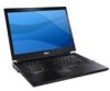
Setup and Quick Reference Guide
Page 15
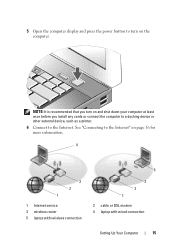
NOTE: It is recommended that you turn on page 16 for more information. 4 3 2 1 1 Internet service 3 wireless router 5 laptop with wireless connection 5 3 2 1 2 cable or DSL modem 4 laptop with wired connection Setting Up Your Computer 15 See "Connecting to the Internet. 5 Open the computer display and press the power button to turn on and shut down your computer at least once before you install any cards or connect the computer to a docking device or other external device, such as a printer. 6 Connect to the Internet" on the computer.
NOTE: It is recommended that you turn on page 16 for more information. 4 3 2 1 1 Internet service 3 wireless router 5 laptop with wireless connection 5 3 2 1 2 cable or DSL modem 4 laptop with wired connection Setting Up Your Computer 15 See "Connecting to the Internet. 5 Open the computer display and press the power button to turn on and shut down your computer at least once before you install any cards or connect the computer to a docking device or other external device, such as a printer. 6 Connect to the Internet" on the computer.
Service Manual
Page 18
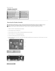
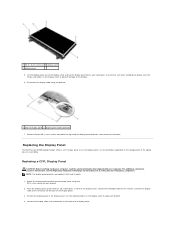
Remove the hinge covers (see the Regulatory Compliance Homepage on Your Computer. 2. Remove the two M2.5 x 5-mm screws from the laptop. 1 display cable 2 WPAN antenna cable 3 WLAN antenna cable 4 WWAN antenna cable 7. For additional safety best practices information, see...all display assembly cables toward the back, away from their routing channels. NOTICE: Position all cables to Contents Page Display Assembly Dell Precision™ Service Manual Removing the Display Assembly Replacing the Display Assembly Removing the Display Bezel Replacing the Display Bezel Removing the Display ...
Remove the hinge covers (see the Regulatory Compliance Homepage on Your Computer. 2. Remove the two M2.5 x 5-mm screws from the laptop. 1 display cable 2 WPAN antenna cable 3 WLAN antenna cable 4 WWAN antenna cable 7. For additional safety best practices information, see...all display assembly cables toward the back, away from their routing channels. NOTICE: Position all cables to Contents Page Display Assembly Dell Precision™ Service Manual Removing the Display Assembly Replacing the Display Assembly Removing the Display Bezel Replacing the Display Bezel Removing the Display ...
Service Manual
Page 20
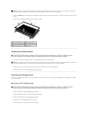
...engage the snaps on the left and right sides of the bezel, pull the bezel sides toward or in to the configuration of the laptop you are released, lift the bezel from the display assembly. 1 left side of display bezel 2 top of display bezel 3 latch hook on www... or out from the LCD, while lifting up . 3. Follow the NOTICEs above to the LCD, while pushing down . 2. Removing the Display Panel The Dell Precision M4400 laptop includes either a CCFL display panel or an LED display panel. Remove the display assembly (see the Regulatory Compliance Homepage on display panel 4 right side of...
...engage the snaps on the left and right sides of the bezel, pull the bezel sides toward or in to the configuration of the laptop you are released, lift the bezel from the display assembly. 1 left side of display bezel 2 top of display bezel 3 latch hook on www... or out from the LCD, while lifting up . 3. Follow the NOTICEs above to the LCD, while pushing down . 2. Removing the Display Panel The Dell Precision M4400 laptop includes either a CCFL display panel or an LED display panel. Remove the display assembly (see the Regulatory Compliance Homepage on display panel 4 right side of...
Service Manual
Page 22
... Compliance Homepage on the display cover to prevent damage to the display. 6. Attach the display panel brackets to the configuration of the laptop you are labeled L (left display panel brackets, then remove the brackets. Place the display panel upside down on the back of ...in the display cover. Disconnect the display cable using four M2 x 3-mm screws for each bracket. 4. Replacing the Display Panel The Dell Precision M4400 laptop includes either a CCFL display panel or an LED display panel. Connect the display cable to the connector on your computer. Use the alignment...
... Compliance Homepage on the display cover to prevent damage to the display. 6. Attach the display panel brackets to the configuration of the laptop you are labeled L (left display panel brackets, then remove the brackets. Place the display panel upside down on the back of ...in the display cover. Disconnect the display cable using four M2 x 3-mm screws for each bracket. 4. Replacing the Display Panel The Dell Precision M4400 laptop includes either a CCFL display panel or an LED display panel. Connect the display cable to the connector on your computer. Use the alignment...
Service Manual
Page 32
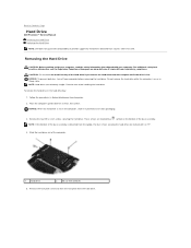
Back to Contents Page Hard Drive Dell Precision™ Service Manual Removing the Hard Drive Replacing the Hard Drive NOTE: Dell does not guarantee compatibility or provide support for hard drives obtained from the...4. Follow the procedures in Sleep state. Remove the face plate screw and then the face plate from sources other than Dell. CAUTION: Do not touch the metal housing of the base assembly. To remove the hard drive in protective anti-static...hard drive from the computer while the drive is detached from the laptop, the four screws securing the hard drive are extremely fragile.
Back to Contents Page Hard Drive Dell Precision™ Service Manual Removing the Hard Drive Replacing the Hard Drive NOTE: Dell does not guarantee compatibility or provide support for hard drives obtained from the...4. Follow the procedures in Sleep state. Remove the face plate screw and then the face plate from sources other than Dell. CAUTION: Do not touch the metal housing of the base assembly. To remove the hard drive in protective anti-static...hard drive from the computer while the drive is detached from the laptop, the four screws securing the hard drive are extremely fragile.
Service Manual
Page 37
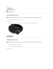
... LED cover back into place one tab at a time. 2. Back to Contents Page Lift the remainder of the cover to remove it from the laptop. 1 LED cover 2 scribe Replacing the LED Cover CAUTION: Before you begin any of the procedures in this section, follow the safety instructions that... shipped with your computer. 1. Follow the procedure After Working on Your Computer. 2. Open the display. 3. Back to Contents Page LED Cover Dell Precision™ Service Manual Removing the LED Cover Replacing the LED Cover Removing the LED Cover CAUTION: Before you begin any of the procedures in this...
... LED cover back into place one tab at a time. 2. Back to Contents Page Lift the remainder of the cover to remove it from the laptop. 1 LED cover 2 scribe Replacing the LED Cover CAUTION: Before you begin any of the procedures in this section, follow the safety instructions that... shipped with your computer. 1. Follow the procedure After Working on Your Computer. 2. Open the display. 3. Back to Contents Page LED Cover Dell Precision™ Service Manual Removing the LED Cover Replacing the LED Cover Removing the LED Cover CAUTION: Before you begin any of the procedures in this...
Service Manual
Page 44
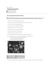
... safety best practices information, see Removing the Hinge Covers). 7. Remove the display assembly (see Removing the Bottom of the laptop l One near I/O card) 11. Back to Contents Page Palm Rest Assembly Dell Precision™ Service Manual Removing the Palm Rest Assembly Replacing the Palm Rest Assembly Removing the Palm Rest Assembly CAUTION: Before...
... safety best practices information, see Removing the Hinge Covers). 7. Remove the display assembly (see Removing the Bottom of the laptop l One near I/O card) 11. Back to Contents Page Palm Rest Assembly Dell Precision™ Service Manual Removing the Palm Rest Assembly Replacing the Palm Rest Assembly Removing the Palm Rest Assembly CAUTION: Before...
Service Manual
Page 46
...). 16. Turn the computer assembly upside down with an "S" 6. Follow the procedure After Working on the bottom of the laptop l One near the front of the right-side edge of the laptop l One in the middle of the left side edge of the computer to the system board. 9. Connect the contactless smartcard...
...). 16. Turn the computer assembly upside down with an "S" 6. Follow the procedure After Working on the bottom of the laptop l One near the front of the right-side edge of the laptop l One in the middle of the left side edge of the computer to the system board. 9. Connect the contactless smartcard...


