Service Manual
Page 4
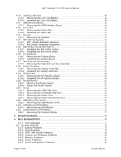
Dell™ Latitude™ XT2 XFR Service Manual 4.10 COIN-CELL BATTERY ...48 4.10.1 Removing the Coin-Cell Battery 48 4.10.2 Installing the Coin-Cell Battery 49 4.11 USB INTERFACE BOARD ...49 4.11.1 Removing the USB Interface Board 49 4.12 STYLUS BAY...50 4.12.1 Removing the Stylus Bay...50 4.12.2 Installing the Stylus...the GPS Module ...71 4.24 CAMERA MODULE (OPTIONAL) ...72 4.24.1 Removing the Camera Module 72 5 SPECIFICATIONS ...73 6 DELL DIAGNOSTICS...74 6.1.1 Error Messages ...77 6.2 SOLVING PROBLEMS...78 6.2.1 Battery Problems ...78 6.2.2 Drive Problems ...78 6.2.3 IEEE 1394 Device...
Dell™ Latitude™ XT2 XFR Service Manual 4.10 COIN-CELL BATTERY ...48 4.10.1 Removing the Coin-Cell Battery 48 4.10.2 Installing the Coin-Cell Battery 49 4.11 USB INTERFACE BOARD ...49 4.11.1 Removing the USB Interface Board 49 4.12 STYLUS BAY...50 4.12.1 Removing the Stylus Bay...50 4.12.2 Installing the Stylus...the GPS Module ...71 4.24 CAMERA MODULE (OPTIONAL) ...72 4.24.1 Removing the Camera Module 72 5 SPECIFICATIONS ...73 6 DELL DIAGNOSTICS...74 6.1.1 Error Messages ...77 6.2 SOLVING PROBLEMS...78 6.2.1 Battery Problems ...78 6.2.2 Drive Problems ...78 6.2.3 IEEE 1394 Device...

Service Manual
Page 16
... user intuitive toggling between the available pointing device according to Pen Only mode. The N-Trig digitizer is not possible. The purpose of detecting a stylus as well as finger touch. Dual Mode is a unique operational mode that only a single hand contact is allowed with the N-trig digitizer. ... Running the diagnostics will switch the digitizer from Pen Only mode to a mouse double-click) will help determine the functionality of range. Dell™ Latitude™ XT2 XFR Service Manual 1.4.3.1.1 Input Mode Selection The N-trig applet has 4 operating modes: Pen Only -
... user intuitive toggling between the available pointing device according to Pen Only mode. The N-Trig digitizer is not possible. The purpose of detecting a stylus as well as finger touch. Dual Mode is a unique operational mode that only a single hand contact is allowed with the N-trig digitizer. ... Running the diagnostics will switch the digitizer from Pen Only mode to a mouse double-click) will help determine the functionality of range. Dell™ Latitude™ XT2 XFR Service Manual 1.4.3.1.1 Input Mode Selection The N-trig applet has 4 operating modes: Pen Only -

Service Manual
Page 17
...touch position is reported. Signals received during the stylus excitation test are below . Pen or touch may be not functional or detected in a certain channel is set to define the result codes. Dell™ Latitude™ XT2 XFR Service Manual After the test is complete, the... results are displayed as illustrated below 11 Stylus excitation No pen excitation certain limit. Pen may be degraded malfunctioning in ...
...touch position is reported. Signals received during the stylus excitation test are below . Pen or touch may be not functional or detected in a certain channel is set to define the result codes. Dell™ Latitude™ XT2 XFR Service Manual After the test is complete, the... results are displayed as illustrated below 11 Stylus excitation No pen excitation certain limit. Pen may be degraded malfunctioning in ...
Service Manual
Page 20
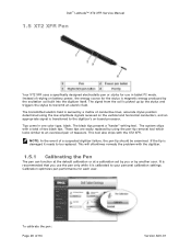
Dell™ Latitude™ XT2 XFR Service Manual 1.5 XT2 XFR Pen Your XT2 XFR uses a specifically designed electrostatic pen or stylus for each user. Tips come in tablet PC mode. If the tip is recommended that you or by the stylus and triggers the stylus to transmit an electric field. It is damaged... an appropriate signal is transferred to an oversized pair of relying on -board processor. This will oftentimes remedy the problem with the XT2 XFR. The signal from the coil is magnetic energy produced by a matrix of a suspected digitizer failure, the pen tip should be...
Dell™ Latitude™ XT2 XFR Service Manual 1.5 XT2 XFR Pen Your XT2 XFR uses a specifically designed electrostatic pen or stylus for each user. Tips come in tablet PC mode. If the tip is recommended that you or by the stylus and triggers the stylus to transmit an electric field. It is damaged... an appropriate signal is transferred to an oversized pair of relying on -board processor. This will oftentimes remedy the problem with the XT2 XFR. The signal from the coil is magnetic energy produced by a matrix of a suspected digitizer failure, the pen tip should be...

Service Manual
Page 25
Dell™ Latitude™ XT2 XFR Service Manual After you complete any replacement procedure, ensure you connect any cards, such as a port replicator, battery slice, or media base, and replace any external devices, cards, and cables before turning on your XT2 XFR. 3 Screw Chart Chassis Location 1 USB/1394... DOOR 2 IO/AUDIO DOOR 3 IO/VGA DOOR 4 POWER DOOR 5 RF PASS THRU 6 STYLUS BAY 7 SNIFFER ASSEMBLY 8 SYSTEM BOARD Screw Part # Qty hinge assy screw...
Dell™ Latitude™ XT2 XFR Service Manual After you complete any replacement procedure, ensure you connect any cards, such as a port replicator, battery slice, or media base, and replace any external devices, cards, and cables before turning on your XT2 XFR. 3 Screw Chart Chassis Location 1 USB/1394... DOOR 2 IO/AUDIO DOOR 3 IO/VGA DOOR 4 POWER DOOR 5 RF PASS THRU 6 STYLUS BAY 7 SNIFFER ASSEMBLY 8 SYSTEM BOARD Screw Part # Qty hinge assy screw...

Service Manual
Page 50
... be replaced later during installation. 4. Follow the procedures in Before Working Inside Your XT2 XFR. 2. Follow the procedures in Before Working Inside Your XT2 XFR. 2. Disconnect the stylus bay connector from the ZIF connectors on the USB Interface board. 5. Disconnect the ...USB interface board to the palm rest. 4.12 Stylus Bay WARNING: Before working inside your XT2 XFR, read the safety information that shipped with your XT2 XFR. Page 50 of 94 Version A00-01 Dell™ Latitude™ XT2 XFR Service Manual 1. For additional safety best practices information...
... be replaced later during installation. 4. Follow the procedures in Before Working Inside Your XT2 XFR. 2. Follow the procedures in Before Working Inside Your XT2 XFR. 2. Disconnect the stylus bay connector from the ZIF connectors on the USB Interface board. 5. Disconnect the ...USB interface board to the palm rest. 4.12 Stylus Bay WARNING: Before working inside your XT2 XFR, read the safety information that shipped with your XT2 XFR. Page 50 of 94 Version A00-01 Dell™ Latitude™ XT2 XFR Service Manual 1. For additional safety best practices information...

Service Manual
Page 51
... Stylus Bay from the bottom chassis by threading the cable and connector through the opening to the chassis. 5. Unthread the cable and connector for the stylus bay. 6. Loosen and remove the screw holding the stylus bay housing to produce a seal. 3. Start by lifting up. Page 51 of 94 Version A00-01 Dell™ Latitude™ XT2 XFR...
... Stylus Bay from the bottom chassis by threading the cable and connector through the opening to the chassis. 5. Unthread the cable and connector for the stylus bay. 6. Loosen and remove the screw holding the stylus bay housing to produce a seal. 3. Start by lifting up. Page 51 of 94 Version A00-01 Dell™ Latitude™ XT2 XFR...

Service Manual
Page 56
...9. Remove the sniffer switch cable from the system board. 6. Disconnect the video connector from the XT2 XFR. 5. Dell™ Latitude™ XT2 XFR Service Manual 4.16 System Board WARNING: Before working inside of 94 Version A00-01 Remove the ...XT2 XFR, read the safety information that shipped with your XT2 XFR. For additional safety best practices information, see the Regulatory Compliance Homepage at www.dell.com/regulatory_compliance. 4.16.1 Removing the System Board 1. Page 56 of the XT2 XFR, disconnect the display cable from the system board. 7. Disconnect the Stylus...
...9. Remove the sniffer switch cable from the system board. 6. Disconnect the video connector from the XT2 XFR. 5. Dell™ Latitude™ XT2 XFR Service Manual 4.16 System Board WARNING: Before working inside of 94 Version A00-01 Remove the ...XT2 XFR, read the safety information that shipped with your XT2 XFR. For additional safety best practices information, see the Regulatory Compliance Homepage at www.dell.com/regulatory_compliance. 4.16.1 Removing the System Board 1. Page 56 of the XT2 XFR, disconnect the display cable from the system board. 7. Disconnect the Stylus...

Service Manual
Page 57
Dell™ Latitude™ XT2 XFR Service Manual 2 3 5 4 1 6 1 Speaker connection 2 Stylus connection 3 Coin-cell battery connection 4 WiFi sniffer connection 5 System board screw (2.5 x 5-mm) 6 System board screw at bracket (2.5 x 8-mm) 10. Carefully lift the gasket surround from the fan housing area and lift the gasket from the XT2 XFR. Page 57 of 94 Version A00-01 Lift the system board up and remove from over the video/antenna cable socket. 11.
Dell™ Latitude™ XT2 XFR Service Manual 2 3 5 4 1 6 1 Speaker connection 2 Stylus connection 3 Coin-cell battery connection 4 WiFi sniffer connection 5 System board screw (2.5 x 5-mm) 6 System board screw at bracket (2.5 x 8-mm) 10. Carefully lift the gasket surround from the fan housing area and lift the gasket from the XT2 XFR. Page 57 of 94 Version A00-01 Lift the system board up and remove from over the video/antenna cable socket. 11.

Service Manual
Page 58
... 94 Version A00-01 Examine the system board to the chassis. 2 3 5 1 4 6 1 Speaker connection 3 Coin-cell battery connection 2 Stylus connection 4 WiFi sniffer connection Page 58 of the system board near the docking connector. 2. Dell™ Latitude™ XT2 XFR Service Manual 4.16.2 Installing the System Board 1. Place the system board into the chassis and seat the...
... 94 Version A00-01 Examine the system board to the chassis. 2 3 5 1 4 6 1 Speaker connection 3 Coin-cell battery connection 2 Stylus connection 4 WiFi sniffer connection Page 58 of the system board near the docking connector. 2. Dell™ Latitude™ XT2 XFR Service Manual 4.16.2 Installing the System Board 1. Place the system board into the chassis and seat the...

Service Manual
Page 59
...coin-cell battery to the system board. 8. Dell™ Latitude™ XT2 XFR Service Manual 5 System board screw (2.5 x 5-mm) 6 System board screw at www.dell.com/regulatory_compliance. 4.17.1 Removing the Heat ...Sink and Fan Assembly 1. Connect the video cable to the system board. 9. Follow the procedures in Before Working Inside Your XT2 XFR. 2. Connect the sniffer switch cable to the system board. 6. Connect the stylus...
...coin-cell battery to the system board. 8. Dell™ Latitude™ XT2 XFR Service Manual 5 System board screw (2.5 x 5-mm) 6 System board screw at www.dell.com/regulatory_compliance. 4.17.1 Removing the Heat ...Sink and Fan Assembly 1. Connect the video cable to the system board. 9. Follow the procedures in Before Working Inside Your XT2 XFR. 2. Connect the sniffer switch cable to the system board. 6. Connect the stylus...


