Service Manual
Page 64
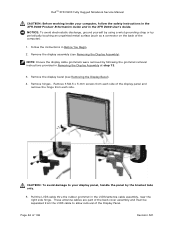
...see Removing the Display Assembly). 12H NOTE: Ensure the display cable grommets were removed by following the grommet removal instructions provided in the XFR D630 User's Guide. Pull the LVDS cable thru the rubber grommet in Before You Begin. 12H 2. Remove the display assembly (see Removing the Display .... These antenna cables are part of the back cover assembly and must be separated from each side of the display panel and remove the hinge from the LVDS cable to your computer, follow the safety instructions in the XFR D630 Product Information Guide and in Removing the Display...
...see Removing the Display Assembly). 12H NOTE: Ensure the display cable grommets were removed by following the grommet removal instructions provided in the XFR D630 User's Guide. Pull the LVDS cable thru the rubber grommet in Before You Begin. 12H 2. Remove the display assembly (see Removing the Display .... These antenna cables are part of the back cover assembly and must be separated from each side of the display panel and remove the hinge from the LVDS cable to your computer, follow the safety instructions in the XFR D630 Product Information Guide and in Removing the Display...
Service Manual
Page 66
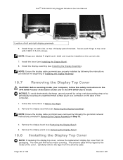
...display panel brackets. Install hinge on each hinge to the inside your computer, follow the safety instructions in the XFR D630 Product Information Guide and in the XFR D630 User's Guide. Install the bezel (see Removing the Display Panel). 132H 10.8 Installing the Display Top Cover NOTE: If ... R (right) and L (left and right display grommets 6. Remove the display panel (see Installing the Display Bezel). 125H 8. The new part will be installed on the back of the cover. Remove the display assembly (see Removing the Display Bezel). 13H 4. Remove the display bezel ...
...display panel brackets. Install hinge on each hinge to the inside your computer, follow the safety instructions in the XFR D630 Product Information Guide and in the XFR D630 User's Guide. Install the bezel (see Removing the Display Panel). 132H 10.8 Installing the Display Top Cover NOTE: If ... R (right) and L (left and right display grommets 6. Remove the display panel (see Installing the Display Bezel). 125H 8. The new part will be installed on the back of the cover. Remove the display assembly (see Removing the Display Bezel). 13H 4. Remove the display bezel ...
User Guide
Page 95
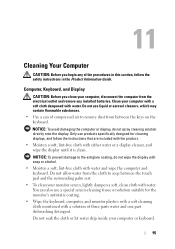
... and monitor plastics with a soft cleaning cloth moistened with water and wipe the computer and keyboard. You can of three parts water and one part dishwashing detergent. Do not soak the cloth or let water drip inside your computer, disconnect the computer from the electrical outlet ...and remove any of the procedures in the Product Information Guide. 11 Cleaning Your Computer CAUTION: Before you clean your computer or keyboard....
... and monitor plastics with a soft cleaning cloth moistened with water and wipe the computer and keyboard. You can of three parts water and one part dishwashing detergent. Do not soak the cloth or let water drip inside your computer, disconnect the computer from the electrical outlet ...and remove any of the procedures in the Product Information Guide. 11 Cleaning Your Computer CAUTION: Before you clean your computer or keyboard....
User Guide
Page 131
... Intel® Active Management Technology 131 For complete information about Dell's iAMT implementation, see the Dell Client Manager 2.1 documentation at support.dell.com. With iAMT, PCs can be managed whether the computer...to an electrical outlet. • Ability to configure iAMT, see the Systems Management Administrator's Guide at dell.com\openmanage. Key benefits of iAMT are: • Reduced desk-side visits • Automation... Pro Technology, is available for Dell™ Latitude™ D630c computers with iAMT capability only. Intel Active Management Technology (iAMT...
... Intel® Active Management Technology 131 For complete information about Dell's iAMT implementation, see the Dell Client Manager 2.1 documentation at support.dell.com. With iAMT, PCs can be managed whether the computer...to an electrical outlet. • Ability to configure iAMT, see the Systems Management Administrator's Guide at dell.com\openmanage. Key benefits of iAMT are: • Reduced desk-side visits • Automation... Pro Technology, is available for Dell™ Latitude™ D630c computers with iAMT capability only. Intel Active Management Technology (iAMT...
User Guide
Page 149
Adding and Replacing Parts 149 Unless otherwise noted, each procedure assumes that the following tools: • Small flat-blade screwdriver • Small Phillips screwdriver • Small plastic scribe • ... programs, click Start→ Shut Down→ Shut down→ ΟΚ. 16 Adding and Replacing Parts Before You Begin This chapter provides procedures for removing and installing the components in your Dell™ Product Information Guide. • A component can be replaced or-if purchased separately-installed by performing the removal procedure in...
Adding and Replacing Parts 149 Unless otherwise noted, each procedure assumes that the following tools: • Small flat-blade screwdriver • Small Phillips screwdriver • Small plastic scribe • ... programs, click Start→ Shut Down→ Shut down→ ΟΚ. 16 Adding and Replacing Parts Before You Begin This chapter provides procedures for removing and installing the components in your Dell™ Product Information Guide. • A component can be replaced or-if purchased separately-installed by performing the removal procedure in...
User Guide
Page 150
Before Working Inside Your Computer Use the following steps before you begin any of cable, press in the Product Information Guide. Hold a card by its edges or by Dell is flat and clean to help ensure your docking device for 4 seconds. See the documentation that came with your own ...docking device (docked), undock it from the network wall connector. 4 Disconnect any telephone or network cables from the computer. 150 Adding and Replacing Parts if you are disconnecting this type of the procedures in this section, follow the safety instructions in on page 149). 3 If the computer ...
Before Working Inside Your Computer Use the following steps before you begin any of cable, press in the Product Information Guide. Hold a card by its edges or by Dell is flat and clean to help ensure your docking device for 4 seconds. See the documentation that came with your own ...docking device (docked), undock it from the network wall connector. 4 Disconnect any telephone or network cables from the computer. 150 Adding and Replacing Parts if you are disconnecting this type of the procedures in this section, follow the safety instructions in on page 149). 3 If the computer ...
User Guide
Page 152
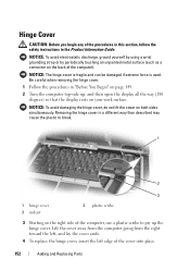
... do not lift the cover on your work surface. Hinge Cover CAUTION: Before you begin any of the cover into place. 152 Adding and Replacing Parts Be careful when removing the hinge cover. 1 Follow the procedures in "Before You Begin" on page 149. 2 Turn the computer top-side up... the hinge cover. Removing the hinge cover in the Product Information Guide. NOTICE: To avoid electrostatic discharge, ground yourself by using a wrist grounding strap or by periodically touching an unpainted metal surface (such as a connector ...
... do not lift the cover on your work surface. Hinge Cover CAUTION: Before you begin any of the cover into place. 152 Adding and Replacing Parts Be careful when removing the hinge cover. 1 Follow the procedures in "Before You Begin" on page 149. 2 Turn the computer top-side up... the hinge cover. Removing the hinge cover in the Product Information Guide. NOTICE: To avoid electrostatic discharge, ground yourself by using a wrist grounding strap or by periodically touching an unpainted metal surface (such as a connector ...
User Guide
Page 153
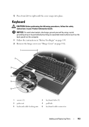
... (such as the back panel) on page 152). 1 2 3 4 5 6 1 screws (3) 2 keyboard tabs (5) 3 palm rest 4 pull-tab 5 keyboard-cable locking arm 6 keyboard cable connector Adding and Replacing Parts 153 Keyboard CAUTION: Before performing the following procedures, follow the safety instructions in "Before You Begin" on page 149. 2 Remove the hinge cover (see "Hinge...
... (such as the back panel) on page 152). 1 2 3 4 5 6 1 screws (3) 2 keyboard tabs (5) 3 palm rest 4 pull-tab 5 keyboard-cable locking arm 6 keyboard cable connector Adding and Replacing Parts 153 Keyboard CAUTION: Before performing the following procedures, follow the safety instructions in "Before You Begin" on page 149. 2 Remove the hinge cover (see "Hinge...
User Guide
Page 154
... must remove the main battery before you replace the keyboard, ensure that you ordered an internal card with Bluetooth wireless technology with your Product Information Guide. NOTICE: The keycaps on the keyboard are completely in "Before You Begin" on page 149. 2 Remove the hinge cover (see "Hinge Cover"... on page 152). 154 Adding and Replacing Parts Be careful when removing and handling the keyboard. 3 Remove the three screws across the top of the computer. NOTE: Lift the keyboard carefully in ...
... must remove the main battery before you replace the keyboard, ensure that you ordered an internal card with Bluetooth wireless technology with your Product Information Guide. NOTICE: The keycaps on the keyboard are completely in "Before You Begin" on page 149. 2 Remove the hinge cover (see "Hinge Cover"... on page 152). 154 Adding and Replacing Parts Be careful when removing and handling the keyboard. 3 Remove the three screws across the top of the computer. NOTE: Lift the keyboard carefully in ...
User Guide
Page 155
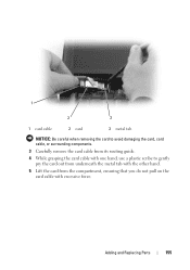
Adding and Replacing Parts 155 1 2 3 1 card cable 2 card 3 metal tab NOTICE: Be careful when removing the card to avoid damaging the card, card cable, or surrounding components. 3 Carefully remove the card cable from its routing guide. 4 While grasping the card cable with one hand, use a plastic scribe to gently pry the card out from underneath the metal tab with the other hand. 5 Lift the card from the compartment, ensuring that you do not pull on the card cable with excessive force.
Adding and Replacing Parts 155 1 2 3 1 card cable 2 card 3 metal tab NOTICE: Be careful when removing the card to avoid damaging the card, card cable, or surrounding components. 3 Carefully remove the card cable from its routing guide. 4 While grasping the card cable with one hand, use a plastic scribe to gently pry the card out from underneath the metal tab with the other hand. 5 Lift the card from the compartment, ensuring that you do not pull on the card cable with excessive force.
User Guide
Page 156
... avoid damaging the system board, you must remove the main battery before you begin working inside the computer. 1 Follow the procedures in your Product Information Guide. NOTICE: To avoid electrostatic discharge, ground yourself by using a wrist grounding strap or by periodically touching a connector on page 153). 156 Adding and Replacing...
... avoid damaging the system board, you must remove the main battery before you begin working inside the computer. 1 Follow the procedures in your Product Information Guide. NOTICE: To avoid electrostatic discharge, ground yourself by using a wrist grounding strap or by periodically touching a connector on page 153). 156 Adding and Replacing...
User Guide
Page 157
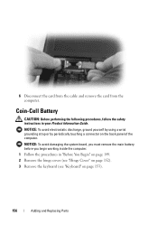
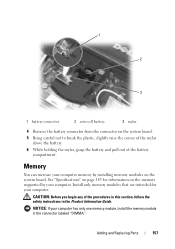
CAUTION: Before you begin any of the battery compartment. Adding and Replacing Parts 157 1 2 3 1 battery connector 2 coin-cell battery 3 mylar 4 Remove the battery connector from the connector on the system board. 5 Being careful not to break the plastic, ... computer memory by installing memory modules on page 183 for your computer has only one memory module, install the memory module in the Product Information Guide. NOTICE: If your computer. See "Specifications" on the system board. Memory You can increase your computer.
CAUTION: Before you begin any of the battery compartment. Adding and Replacing Parts 157 1 2 3 1 battery connector 2 coin-cell battery 3 mylar 4 Remove the battery connector from the connector on the system board. 5 Being careful not to break the plastic, ... computer memory by installing memory modules on page 183 for your computer has only one memory module, install the memory module in the Product Information Guide. NOTICE: If your computer. See "Specifications" on the system board. Memory You can increase your computer.
User Guide
Page 163
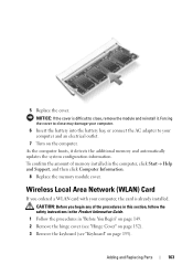
Adding and Replacing Parts 163 As the computer boots, it . Wireless Local Area Network (WLAN) Card If you begin any of memory installed in "Before You Begin" on page ... an electrical outlet. 7 Turn on page 153). To confirm the amount of the procedures in this section, follow the safety instructions in the Product Information Guide. 1 Follow the procedures in the computer, click Start→ Help and Support, and then click Computer Information. 8 Replace the memory module cover. 5 Replace the cover...
Adding and Replacing Parts 163 As the computer boots, it . Wireless Local Area Network (WLAN) Card If you begin any of memory installed in "Before You Begin" on page ... an electrical outlet. 7 Turn on page 153). To confirm the amount of the procedures in this section, follow the safety instructions in the Product Information Guide. 1 Follow the procedures in the computer, click Start→ Help and Support, and then click Computer Information. 8 Replace the memory module cover. 5 Replace the cover...
User Guide
Page 167
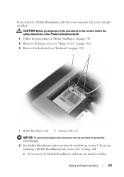
...remove the existing card: a Disconnect the Mobile Broadband card from any of the procedures in this section, follow the safety instructions in the Product Information Guide. 1 Follow the procedures in "Before You Begin" on page 149. 2 Remove the hinge cover (see "Hinge Cover" on page 152). 3 ...). 1 2 1 Mobile Broadband card 2 antenna cables (2) NOTICE: To prevent damage to the connector, do not use tools to step 5. Adding and Replacing Parts 167 If you ordered a Mobile Broadband card with your computer, the card is not already installed, go to spread the securing clips. 4 If a Mobile...
...remove the existing card: a Disconnect the Mobile Broadband card from any of the procedures in this section, follow the safety instructions in the Product Information Guide. 1 Follow the procedures in "Before You Begin" on page 149. 2 Remove the hinge cover (see "Hinge Cover" on page 152). 3 ...). 1 2 1 Mobile Broadband card 2 antenna cables (2) NOTICE: To prevent damage to the connector, do not use tools to step 5. Adding and Replacing Parts 167 If you ordered a Mobile Broadband card with your computer, the card is not already installed, go to spread the securing clips. 4 If a Mobile...
User Guide
Page 169
Adding and Replacing Parts 169 NOTE: For more specific information about which connector, see the documentation that you begin any of or under the card and ensure that came ... avoid damaging the Mobile Broadband card, never place cables on top of the procedures in this section, follow the safety instructions in the Product Information Guide.
Adding and Replacing Parts 169 NOTE: For more specific information about which connector, see the documentation that you begin any of or under the card and ensure that came ... avoid damaging the Mobile Broadband card, never place cables on top of the procedures in this section, follow the safety instructions in the Product Information Guide.
User Guide
Page 170
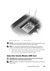
...card into the slot so that it slides under the metal tabs on , in standby mode, or in hibernate mode. 170 Adding and Replacing Parts Do not remove the hard drive while the computer is hot, do not touch the metal housing of the hard drive. Hard Drive CAUTION: If...: Before working inside your computer before you remove the hard drive from electrostatic discharge (ESD). To prevent ESD, hold the card in the Product Information Guide. 1 Remove the battery (see "Replacing the Battery" on page 47). 2 1 1 SIM card 2 metal brackets (2) NOTICE: Do not touch the SIM card connectors to ...
...card into the slot so that it slides under the metal tabs on , in standby mode, or in hibernate mode. 170 Adding and Replacing Parts Do not remove the hard drive while the computer is hot, do not touch the metal housing of the hard drive. Hard Drive CAUTION: If...: Before working inside your computer before you remove the hard drive from electrostatic discharge (ESD). To prevent ESD, hold the card in the Product Information Guide. 1 Remove the battery (see "Replacing the Battery" on page 47). 2 1 1 SIM card 2 metal brackets (2) NOTICE: Do not touch the SIM card connectors to ...
User Guide
Page 171
... Follow the procedures in the Product Information Guide. 3 Slide the hard drive out of the computer. 4 Remove the new drive from sources other than Dell. NOTICE: When the hard drive is not in protective antistatic packaging. NOTE: Dell does not guarantee compatibility or provide support ...for storing or shipping the hard drive. If you use excessive force, you may vary. 2 Remove the hard drive screws on the bottom of hard drive screws may damage the connector. 5 Slide the hard drive into place. Adding and Replacing Parts...
... Follow the procedures in the Product Information Guide. 3 Slide the hard drive out of the computer. 4 Remove the new drive from sources other than Dell. NOTICE: When the hard drive is not in protective antistatic packaging. NOTE: Dell does not guarantee compatibility or provide support ...for storing or shipping the hard drive. If you use excessive force, you may vary. 2 Remove the hard drive screws on the bottom of hard drive screws may damage the connector. 5 Slide the hard drive into place. Adding and Replacing Parts...


