User Manual
Page 11
... or trademarks of Microsoft Corporation in this text: Dell™, the DELL logo, Dell Precision™, Precision ON™, ExpressCharge™, Latitude™, Latitude ON™, OptiPlex™, Vostro™, and Wi-Fi Catcher™ are trademarks of Dell Inc. is a trademark owned by the Blu-ray...11 Trademarks used in the United States and/or other countries. AMD® is a registered trademark and owned by Dell Inc. © 2012 Dell Inc. The Bluetooth® word mark is a registered trademark and AMD Opteron™, AMD Phenom™, AMD Sempron™, AMD Athlon...
... or trademarks of Microsoft Corporation in this text: Dell™, the DELL logo, Dell Precision™, Precision ON™, ExpressCharge™, Latitude™, Latitude ON™, OptiPlex™, Vostro™, and Wi-Fi Catcher™ are trademarks of Dell Inc. is a trademark owned by the Blu-ray...11 Trademarks used in the United States and/or other countries. AMD® is a registered trademark and owned by Dell Inc. © 2012 Dell Inc. The Bluetooth® word mark is a registered trademark and AMD Opteron™, AMD Phenom™, AMD Sempron™, AMD Athlon...
Owner's Manual
Page 2
...8482; are trademarks of your computer. The Bluetooth® word mark is under license. and any use of Dell Inc. is a registered trademark and owned by the Bluetooth® SIG, Inc. Notes, Cautions,... and Warnings NOTE: A NOTE indicates important information that helps you how to hardware or loss of Intel Corporation in the United States and/or other countries. and other countries. Trademarks used in this text: Dell™, the DELL logo, Dell Precision™, Precision ON™,ExpressCharge™, Latitude™, Latitude...
...8482; are trademarks of your computer. The Bluetooth® word mark is under license. and any use of Dell Inc. is a registered trademark and owned by the Bluetooth® SIG, Inc. Notes, Cautions,... and Warnings NOTE: A NOTE indicates important information that helps you how to hardware or loss of Intel Corporation in the United States and/or other countries. and other countries. Trademarks used in this text: Dell™, the DELL logo, Dell Precision™, Precision ON™,ExpressCharge™, Latitude™, Latitude...
Owner's Manual
Page 4
Removing the Processor...26 Installing the Processor...26 Removing the Bluetooth Card...26 Installing the Bluetooth Card...28 Removing the Coin-Cell Battery...28 Installing the Coin-Cell Battery...28 Removing the ExpressCard Cage...29 Installing the ExpressCard Cage...29 Removing ...
Removing the Processor...26 Installing the Processor...26 Removing the Bluetooth Card...26 Installing the Bluetooth Card...28 Removing the Coin-Cell Battery...28 Installing the Coin-Cell Battery...28 Removing the ExpressCard Cage...29 Installing the ExpressCard Cage...29 Removing ...

Owner's Manual
Page 26
... procedures in Before Working Inside Your Computer. 2. Align the notches on the processor and the socket, and insert the processor into the socket. 2. Removing the Bluetooth Card 1. Follow the procedures in Before Working Inside Your Computer. 2. Removing the Processor 1. Follow the procedures in After Working Inside Your Computer.
... procedures in Before Working Inside Your Computer. 2. Align the notches on the processor and the socket, and insert the processor into the socket. 2. Removing the Bluetooth Card 1. Follow the procedures in Before Working Inside Your Computer. 2. Removing the Processor 1. Follow the procedures in After Working Inside Your Computer.
Owner's Manual
Page 27
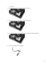
Lift up the card along the bottom edge and remove it from the bluetooth card. 27 Disconnect the cable from the housing. 5. Remove the screw that secures the bluetooth card to the computer. 4. c) base cover 3. Disconnect the bluetooth cable from the system board and remove the card from the computer. 6.
Lift up the card along the bottom edge and remove it from the bluetooth card. 27 Disconnect the cable from the housing. 5. Remove the screw that secures the bluetooth card to the computer. 4. c) base cover 3. Disconnect the bluetooth cable from the system board and remove the card from the computer. 6.
Owner's Manual
Page 28
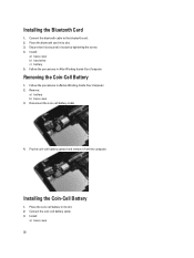
... screw. 4. Place the coin-cell battery in its slot. 2. Install: a) base cover 28 Ensure that it from the computer. Remove: a) battery b) base cover 3. Place the bluetooth card in its slot. 3. Installing the Coin-Cell Battery 1. Removing the Coin-Cell Battery 1. Install: a) base cover b) hard drive c) battery 5. Connect the coin-cell battery...
... screw. 4. Place the coin-cell battery in its slot. 2. Install: a) base cover 28 Ensure that it from the computer. Remove: a) battery b) base cover 3. Place the bluetooth card in its slot. 3. Installing the Coin-Cell Battery 1. Removing the Coin-Cell Battery 1. Install: a) base cover b) hard drive c) battery 5. Connect the coin-cell battery...
Owner's Manual
Page 29
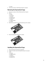
...cage to the computer. 3. Remove the ExpressCard cage from the computer. Install: a) palmrest b) display assembly c) keyboard d) keyboard trim e) bluetooth card 29 Follow the procedures in After Working Inside Your Computer. Place the ExpressCard cage into its compartment. 2. Installing the ExpressCard Cage 1. ... cage to the computer. 4. Removing the ExpressCard Cage 1. b) battery 4. Remove: a) battery b) base cover c) hard drive d) bluetooth card e) keyboard trim f) keyboard g) display assembly h) palmrest 3. Follow the procedures in Before Working Inside Your Computer. 2.
...cage to the computer. 3. Remove the ExpressCard cage from the computer. Install: a) palmrest b) display assembly c) keyboard d) keyboard trim e) bluetooth card 29 Follow the procedures in After Working Inside Your Computer. Place the ExpressCard cage into its compartment. 2. Installing the ExpressCard Cage 1. ... cage to the computer. 4. Removing the ExpressCard Cage 1. b) battery 4. Remove: a) battery b) base cover c) hard drive d) bluetooth card e) keyboard trim f) keyboard g) display assembly h) palmrest 3. Follow the procedures in Before Working Inside Your Computer. 2.
Owner's Manual
Page 30
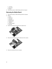
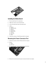
f) hard drive g) base cover h) battery 4. Remove the media board from the system board. 4. Remove: a) battery b) base cover c) hard drive d) bluetooth card e) keyboard trim f) keyboard g) display assembly h) palmrest 3. Remove the screws that secure the media board to the computer. 5. Removing the Media Board 1. Follow the procedures in After Working Inside Your Computer. Disconnect the media board cable from the computer. 30 Follow the procedures in Before Working Inside Your Computer. 2.
f) hard drive g) base cover h) battery 4. Remove the media board from the system board. 4. Remove: a) battery b) base cover c) hard drive d) bluetooth card e) keyboard trim f) keyboard g) display assembly h) palmrest 3. Remove the screws that secure the media board to the computer. 5. Removing the Media Board 1. Follow the procedures in After Working Inside Your Computer. Disconnect the media board cable from the computer. 30 Follow the procedures in Before Working Inside Your Computer. 2.
Owner's Manual
Page 31
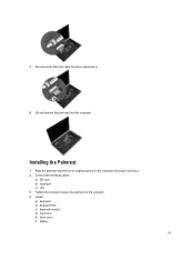
Removing the Power-Connector Port 1. Install: a) palmrest b) display assembly c) keyboard d) keyboard trim e) bluetooth card f) hard drive g) base cover h) battery 5. Disconnect the power-connector cable from the system board. 4. Connect the media board cable to the computer. 31 Follow ...
Removing the Power-Connector Port 1. Install: a) palmrest b) display assembly c) keyboard d) keyboard trim e) bluetooth card f) hard drive g) base cover h) battery 5. Disconnect the power-connector cable from the system board. 4. Connect the media board cable to the computer. 31 Follow ...
Owner's Manual
Page 33
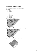
Follow the procedures in Before Working Inside Your Computer. 2. Disconnect the power LED board cable. 4. Remove the power LED board from the display assembly. 33 Remove the screw securing the power LED board to the display assembly. 5. Remove: a) battery b) base cover c) hard drive d) bluetooth module e) keyboard trim f) keyboard g) display assembly h) display bezel i) display panel 3. Removing the Power LED Board 1.
Follow the procedures in Before Working Inside Your Computer. 2. Disconnect the power LED board cable. 4. Remove the power LED board from the display assembly. 33 Remove the screw securing the power LED board to the display assembly. 5. Remove: a) battery b) base cover c) hard drive d) bluetooth module e) keyboard trim f) keyboard g) display assembly h) display bezel i) display panel 3. Removing the Power LED Board 1.
Owner's Manual
Page 34
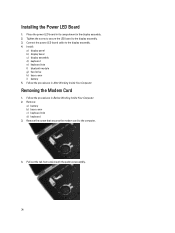
... d) keyboard 3. Follow the procedures in Before Working Inside Your Computer. 2. Installing the Power LED Board 1. Install: a) display panel b) display bezel c) display assembly d) keyboard e) keyboard trim f) bluetooth module g) hard drive h) base cover i) battery 5. Pull out the tab from underneath the palmrest assembly. 34
... d) keyboard 3. Follow the procedures in Before Working Inside Your Computer. 2. Installing the Power LED Board 1. Install: a) display panel b) display bezel c) display assembly d) keyboard e) keyboard trim f) bluetooth module g) hard drive h) base cover i) battery 5. Pull out the tab from underneath the palmrest assembly. 34
Owner's Manual
Page 35
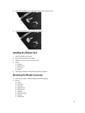
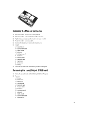
5. Hold and remove the modem card from the slot. 6. Ensure that the modem card is seated. 3. Remove: a) battery b) base cover c) hard drive d) bluetooth card e) keyboard trim f) keyboard g) display assembly h) palmrest i) media board 35 Use the tab and pull the lower right edge of the modem card from the ...
5. Hold and remove the modem card from the slot. 6. Ensure that the modem card is seated. 3. Remove: a) battery b) base cover c) hard drive d) bluetooth card e) keyboard trim f) keyboard g) display assembly h) palmrest i) media board 35 Use the tab and pull the lower right edge of the modem card from the ...
Owner's Manual
Page 37
...modem-connector bracket on the connector. 3. Install: a) system board b) ExpressCard cage c) media board d) palmrest e) display assembly f) keyboard g) keyboard trim h) bluetooth card i) hard drive j) base cover k) battery 7. Connect the modem card cable to secure the modem connector bracket. 4. Follow the procedures in its compartment.... procedures in Before Working Inside Your Computer. 2. Remove: a) battery b) base cover c) hard drive d) optical drive e) bluetooth card f) keyboard trim g) keyboard h) display assembly i) palmrest j) media board k) ExpressCard cage l) system board 37
...modem-connector bracket on the connector. 3. Install: a) system board b) ExpressCard cage c) media board d) palmrest e) display assembly f) keyboard g) keyboard trim h) bluetooth card i) hard drive j) base cover k) battery 7. Connect the modem card cable to secure the modem connector bracket. 4. Follow the procedures in its compartment.... procedures in Before Working Inside Your Computer. 2. Remove: a) battery b) base cover c) hard drive d) optical drive e) bluetooth card f) keyboard trim g) keyboard h) display assembly i) palmrest j) media board k) ExpressCard cage l) system board 37
Owner's Manual
Page 38
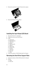
... Working Inside Your Computer. Remove the I /O board. 3. Remove: a) battery b) base cover 38 3. Install: a) system board b) ExpressCard cage c) media board d) palmrest e) display assembly f) keyboard g) keyboard trim h) bluetooth card i) hard drive j) optical drive k) base cover l) battery 4. Tighten the screws to the computer. 4.
... Working Inside Your Computer. Remove the I /O board. 3. Remove: a) battery b) base cover 38 3. Install: a) system board b) ExpressCard cage c) media board d) palmrest e) display assembly f) keyboard g) keyboard trim h) bluetooth card i) hard drive j) optical drive k) base cover l) battery 4. Tighten the screws to the computer. 4.
Owner's Manual
Page 39
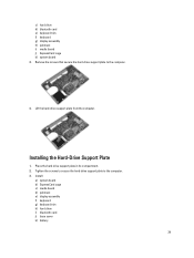
.... 4. Install: a) system board b) ExpressCard cage c) media board d) palmrest e) display assembly f) keyboard g) keyboard trim h) hard drive i) bluetooth card j) base cover k) battery 39 Lift the hard-drive support plate from the computer. Place the hard-drive support plate in its compartment. ...2. c) hard drive d) bluetooth card e) keyboard trim f) keyboard g) display assembly h) palmrest i) media board j) ExpressCard cage k) system board 3. Installing the Hard-Drive Support...
.... 4. Install: a) system board b) ExpressCard cage c) media board d) palmrest e) display assembly f) keyboard g) keyboard trim h) hard drive i) bluetooth card j) base cover k) battery 39 Lift the hard-drive support plate from the computer. Place the hard-drive support plate in its compartment. ...2. c) hard drive d) bluetooth card e) keyboard trim f) keyboard g) display assembly h) palmrest i) media board j) ExpressCard cage k) system board 3. Installing the Hard-Drive Support...
Owner's Manual
Page 40
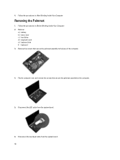
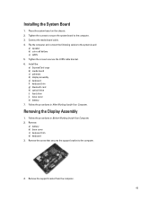
Remove: a) battery b) base cover c) hard drive d) bluetooth card e) keyboard trim f) keyboard 3. Remove the screws that secure the palmrest assembly to the base of the computer. 4. Disconnect the LED cable from the system board. 40 Follow the procedures in After Working Inside Your Computer. 4. Disconnect the touchpad cable from the system board. 6. Flip the computer over and remove the screws that secure the palmrest assembly to the computer. 5. Follow the procedures in Before Working Inside Your Computer. 2. Removing the Palmrest 1.
Remove: a) battery b) base cover c) hard drive d) bluetooth card e) keyboard trim f) keyboard 3. Remove the screws that secure the palmrest assembly to the base of the computer. 4. Disconnect the LED cable from the system board. 40 Follow the procedures in After Working Inside Your Computer. 4. Disconnect the touchpad cable from the system board. 6. Flip the computer over and remove the screws that secure the palmrest assembly to the computer. 5. Follow the procedures in Before Working Inside Your Computer. 2. Removing the Palmrest 1.
Owner's Manual
Page 41
7. Align the palmrest assembly to the computer. 4. Installing the Palmrest 1. Install: a) keyboard b) keyboard trim c) bluetooth module d) hard drive e) base cover f) battery 41 Connect the following cables: a) SD card b) touchpad c) LED 3. Lift and remove the palmrest from the system board. 8. Tighten the screws to secure the palmrest to its original position in the computer and snap it into place. 2. Disconnect the SD card cable from the computer.
7. Align the palmrest assembly to the computer. 4. Installing the Palmrest 1. Install: a) keyboard b) keyboard trim c) bluetooth module d) hard drive e) base cover f) battery 41 Connect the following cables: a) SD card b) touchpad c) LED 3. Lift and remove the palmrest from the system board. 8. Tighten the screws to secure the palmrest to its original position in the computer and snap it into place. 2. Disconnect the SD card cable from the computer.
Owner's Manual
Page 42
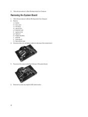
Follow the procedures in After Working Inside Your Computer. Remove the screw securing the LVDS cable bracket. 42 Disconnect the coin-cell battery cable from the base of the system board. 4. Follow the procedures in Before Working Inside Your Computer. 2. Removing the System Board 1. Disconnect the camera cable from the base of the system board. 5. Remove: a) battery b) base cover c) hard drive d) optical drive e) bluetooth card f) keyboard trim g) keyboard h) display assembly i) palmrest j) media board k) ExpressCard cage 3. 5.
Follow the procedures in After Working Inside Your Computer. Remove the screw securing the LVDS cable bracket. 42 Disconnect the coin-cell battery cable from the base of the system board. 4. Follow the procedures in Before Working Inside Your Computer. 2. Removing the System Board 1. Disconnect the camera cable from the base of the system board. 5. Remove: a) battery b) base cover c) hard drive d) optical drive e) bluetooth card f) keyboard trim g) keyboard h) display assembly i) palmrest j) media board k) ExpressCard cage 3. 5.
Owner's Manual
Page 45
... bracket. 6. Tighten the screw to the system board: a) speaker b) coin-cell battery c) LVDS 5. Install the: a) ExpressCard cage b) media board c) palmrest d) display assembly e) keyboard f) keyboard trim g) bluetooth card h) optical drive i) hard drive j) base cover k) battery 7. Follow the procedures in After Working Inside Your Computer. Place the system board on the chassis. 2. Connect...
... bracket. 6. Tighten the screw to the system board: a) speaker b) coin-cell battery c) LVDS 5. Install the: a) ExpressCard cage b) media board c) palmrest d) display assembly e) keyboard f) keyboard trim g) bluetooth card h) optical drive i) hard drive j) base cover k) battery 7. Follow the procedures in After Working Inside Your Computer. Place the system board on the chassis. 2. Connect...
Owner's Manual
Page 51
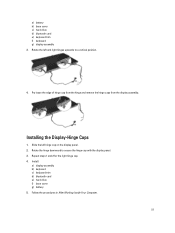
Install: a) display assembly b) keyboard c) keyboard trim d) bluetooth card e) hard drive f) base cover g) battery 5. Slide the left and right hinges upwards to secure the hinge cap with the display panel. 3. Rotate the hinge ... of hinge cap from the hinge and remove the hinge caps from the display assembly. Installing the Display-Hinge Caps 1. a) battery b) base cover c) hard drive d) bluetooth card e) keyboard trim f) keyboard g) display assembly 3. Repeat steps 1 and 2 for the right hinge cap. 4.
Install: a) display assembly b) keyboard c) keyboard trim d) bluetooth card e) hard drive f) base cover g) battery 5. Slide the left and right hinges upwards to secure the hinge cap with the display panel. 3. Rotate the hinge ... of hinge cap from the hinge and remove the hinge caps from the display assembly. Installing the Display-Hinge Caps 1. a) battery b) base cover c) hard drive d) bluetooth card e) keyboard trim f) keyboard g) display assembly 3. Repeat steps 1 and 2 for the right hinge cap. 4.


