Service Manual
Page 5
Dell™ Latitude™ E6400 XFR Service Manual 23 SMARTCARD ASSEMBLY ...50 23.1 REMOVING THE SMARTCARD ASSEMBLY ...50 23.2 REPLACING THE SMARTCARD ASSEMBLY ...51 24 HARD DRIVE...52 24.1 REMOVING THE HARD DRIVE...52 24.2 REPLACING THE HARD DRIVE ...53 25 MODULAR DRIVE...53 25.1 REMOVING THE MODULAR DRIVE...53 25.2 REPLACING THE MODULAR DRIVE ...53 26 SYSTEM BOARD ASSEMBLY ...54 26.1 REMOVING THE...
Dell™ Latitude™ E6400 XFR Service Manual 23 SMARTCARD ASSEMBLY ...50 23.1 REMOVING THE SMARTCARD ASSEMBLY ...50 23.2 REPLACING THE SMARTCARD ASSEMBLY ...51 24 HARD DRIVE...52 24.1 REMOVING THE HARD DRIVE...52 24.2 REPLACING THE HARD DRIVE ...53 25 MODULAR DRIVE...53 25.1 REMOVING THE MODULAR DRIVE...53 25.2 REPLACING THE MODULAR DRIVE ...53 26 SYSTEM BOARD ASSEMBLY ...54 26.1 REMOVING THE...
Service Manual
Page 8
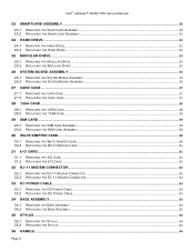
Dell™ Latitude™ E6400 XFR Service Manual System board failure has occurred. has occurred. System failed on Dell computers. Reseat the LCD cable (see Hard Drive). If the problem persists, contact Dell Support. A possible modem failure has occurred. Click Start→ Help and ... LCD failure has occurred. If the problem persists, contact Dell Support. If the problem persists, contact Dell Support. Reseat the hard drive (see Display Assembly). If the problem persists, contact Dell Support. Type hardware troubleshooter in hardware with your computer. ...
Dell™ Latitude™ E6400 XFR Service Manual System board failure has occurred. has occurred. System failed on Dell computers. Reseat the LCD cable (see Hard Drive). If the problem persists, contact Dell Support. A possible modem failure has occurred. Click Start→ Help and ... LCD failure has occurred. If the problem persists, contact Dell Support. If the problem persists, contact Dell Support. Reseat the hard drive (see Display Assembly). If the problem persists, contact Dell Support. Type hardware troubleshooter in hardware with your computer. ...
Service Manual
Page 9
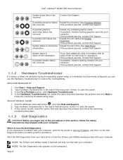
... see a message stating that no diagnostics utility partition has been found , run (see Starting the Dell Diagnostics From the Drivers and Utilities Media). Dell™ Latitude™ E6400 XFR Service Manual Starting the Dell Diagnostics From Your Hard Drive Before running the Dell Diagnostics, enter system setup to review your computer's configuration information, and ensure that the device you...
... see a message stating that no diagnostics utility partition has been found , run (see Starting the Dell Diagnostics From the Drivers and Utilities Media). Dell™ Latitude™ E6400 XFR Service Manual Starting the Dell Diagnostics From Your Hard Drive Before running the Dell Diagnostics, enter system setup to review your computer's configuration information, and ensure that the device you...
Service Manual
Page 14
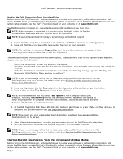
.... If your administrator to continue the desired action. 4. Contact Dell Support. Click Start and click My Computer. 2. Windows Vista: 1. NOTE: Your computer supports only IEEE 1394a standard. Dell™ Latitude™ E6400 XFR Service Manual Hard Drive Problems RUN CHECK DISK - Windows XP: 1. Right-click Local...Computer. 2. Click Properties→ Tools→ Check Now. For more information on using the system setup program, see the Dell™ Technology Guide on the computer, click Continue; Windows XP: 5. Windows Vista: Click Start → Control Panel→...
.... If your administrator to continue the desired action. 4. Contact Dell Support. Click Start and click My Computer. 2. Windows Vista: 1. NOTE: Your computer supports only IEEE 1394a standard. Dell™ Latitude™ E6400 XFR Service Manual Hard Drive Problems RUN CHECK DISK - Windows XP: 1. Right-click Local...Computer. 2. Click Properties→ Tools→ Check Now. For more information on using the system setup program, see the Dell™ Technology Guide on the computer, click Continue; Windows XP: 5. Windows Vista: Click Start → Control Panel→...
Service Manual
Page 15
... TO CHECK THE HARD DRIVE, FLOPPY DISKS, CDS, OR DVDS Page 15 Click to select the program that your computer meets the minimum hardware requirements needed to run the software. Press simultaneously to 10 seconds (until the computer turns off ), and then restart your computer. Click End Task. Dell™ Latitude™ E6400 XFR Service Manual...
... TO CHECK THE HARD DRIVE, FLOPPY DISKS, CDS, OR DVDS Page 15 Click to select the program that your computer meets the minimum hardware requirements needed to run the software. Press simultaneously to 10 seconds (until the computer turns off ), and then restart your computer. Click End Task. Dell™ Latitude™ E6400 XFR Service Manual...
Service Manual
Page 51
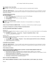
...keyboard, palm rest overlay, LED cover, display assembly, LCD cable channel covers and bottom access panel (see Removing the Hard Drive). 4. Remove the hard drive (see Replacing the Palm Rest). 8. Slide the smartcard housing left until the screw holes are aligned with the tabs...Smartcard connector 2 M2 x 3-mm screws (2) 3 Chassis hooks (5) 7. Remove the two M2 x 3-mm screws from the system board. 6. Dell™ Latitude™ E6400 XFR Service Manual 2. Lift up to the chamber ceiling. Set the smartcard assembly in After Working on the base assembly. 2. Remove the tape backing...
...keyboard, palm rest overlay, LED cover, display assembly, LCD cable channel covers and bottom access panel (see Removing the Hard Drive). 4. Remove the hard drive (see Replacing the Palm Rest). 8. Slide the smartcard housing left until the screw holes are aligned with the tabs...Smartcard connector 2 M2 x 3-mm screws (2) 3 Chassis hooks (5) 7. Remove the two M2 x 3-mm screws from the system board. 6. Dell™ Latitude™ E6400 XFR Service Manual 2. Lift up to the chamber ceiling. Set the smartcard assembly in After Working on the base assembly. 2. Remove the tape backing...
Service Manual
Page 52
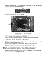
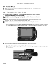
NOTE: See hard drive removal instructions adhered to pull the hard drive from the compartment. Dell™ Latitude™ E6400 XFR Service Manual 24 Hard Drive NOTE: Dell does not guarantee compatibility or provide support for hard drives obtained from the computer while the drive is on or in Before Working on Your Computer, open the hard disk drive door located on the left side panel by...
NOTE: See hard drive removal instructions adhered to pull the hard drive from the compartment. Dell™ Latitude™ E6400 XFR Service Manual 24 Hard Drive NOTE: Dell does not guarantee compatibility or provide support for hard drives obtained from the computer while the drive is on or in Before Working on Your Computer, open the hard disk drive door located on the left side panel by...
Service Manual
Page 53
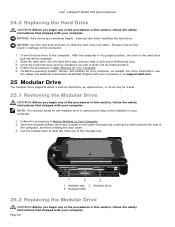
... this section, follow the safety instructions that shipped with your computer. Dell™ Latitude™ E6400 XFR Service Manual 24.2 Replacing the Hard Drive CAUTION: Before you begin any of the procedures in this section, follow the safety instructions that shipped with your computer. NOTICE: Hard drives are extremely fragile. Follow the procedures in After Working on your...
... this section, follow the safety instructions that shipped with your computer. Dell™ Latitude™ E6400 XFR Service Manual 24.2 Replacing the Hard Drive CAUTION: Before you begin any of the procedures in this section, follow the safety instructions that shipped with your computer. NOTICE: Hard drives are extremely fragile. Follow the procedures in After Working on your...
Service Manual
Page 54
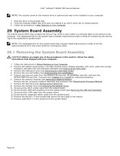
... be installed on Your Computer. 2. Remove the modular drive (see Removing the Hard Drive). 8. Disconnect the SIM card assembly from the system board. Disconnect the Wi-Fi sniffer cable from the system board. 12. Disconnect the 1394 cable from the system board. 10. Dell™ Latitude™ E6400 XFR Service Manual NOTE: The security screw on the...
... be installed on Your Computer. 2. Remove the modular drive (see Removing the Hard Drive). 8. Disconnect the SIM card assembly from the system board. Disconnect the Wi-Fi sniffer cable from the system board. 12. Disconnect the 1394 cable from the system board. 10. Dell™ Latitude™ E6400 XFR Service Manual NOTE: The security screw on the...
Service Manual
Page 56
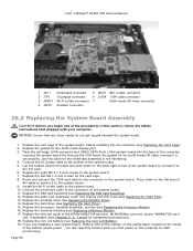
...the number on the yellow label, located on the computer for AMT provisioning. NOTICE: Ensure that shipped with your computer. Page 56 Replace the hard drive (see Chapters 5, 6, 7 and 8 for the smartcard assembly is not interfering. 4. Connect the DC power cable to the I/O card.... VGA Panel, the gasket for the multi-mode HD video connector is set properly, and the cable for replacement procedures). 18. Dell™ Latitude™ E6400 XFR Service Manual 1 JSC1 Smartcard connector 5 JBIO1 BIO reader connector 2 JTP1 Touchpad connector 6 J1394 1394 cable connector 3 JSNIF1 Wi-...
...the number on the yellow label, located on the computer for AMT provisioning. NOTICE: Ensure that shipped with your computer. Page 56 Replace the hard drive (see Chapters 5, 6, 7 and 8 for the smartcard assembly is not interfering. 4. Connect the DC power cable to the I/O card.... VGA Panel, the gasket for the multi-mode HD video connector is set properly, and the cable for replacement procedures). 18. Dell™ Latitude™ E6400 XFR Service Manual 1 JSC1 Smartcard connector 5 JBIO1 BIO reader connector 2 JTP1 Touchpad connector 6 J1394 1394 cable connector 3 JSNIF1 Wi-...
Setup and Features Information Tech Sheet
Page 3
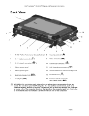
...Fan noise is running. Page 3 The computer turns on the fan when the computer gets hot. Do not store your Dell™ computer in the air vents. Dell™ Latitude™ E6400 XFR Setup and Features Information Back View 1 2 3 4 5 6 7 8 9 1 PR-481™ Ultra-Performance Chassis.../power lights 10 eSATA/USB connector ( ) 11 USB PowerShare connector ( ) 12 Sealed QuadCool™ thermal management 6 Multimode Display Port ( ) 13 Hard Disk Drive ( ) 7 AC adapter ( ) 14 Enclosed Smart-card reader (see Smart Cards) ( ) WARNING: Do not block, push objects into, or ...
...Fan noise is running. Page 3 The computer turns on the fan when the computer gets hot. Do not store your Dell™ computer in the air vents. Dell™ Latitude™ E6400 XFR Setup and Features Information Back View 1 2 3 4 5 6 7 8 9 1 PR-481™ Ultra-Performance Chassis.../power lights 10 eSATA/USB connector ( ) 11 USB PowerShare connector ( ) 12 Sealed QuadCool™ thermal management 6 Multimode Display Port ( ) 13 Hard Disk Drive ( ) 7 AC adapter ( ) 14 Enclosed Smart-card reader (see Smart Cards) ( ) WARNING: Do not block, push objects into, or ...

Setup and Features Information Tech Sheet
Page 6
Use the tab on the left side panel by pushing the latch towards the rear of the battery to remove the battery from the computer. Battery Installation 1. Rotate the door into place and push shut. 3. Open the hard drive access door located on the edge of the computer, Page 6 Ensure the door is in the fully closed and locked position. Insert battery until you hear a click and a mechanical stop. 2. Hard Drive Removal 1. Dell™ Latitude™ E6400 XFR Setup and Features Information 4.
Use the tab on the left side panel by pushing the latch towards the rear of the battery to remove the battery from the computer. Battery Installation 1. Rotate the door into place and push shut. 3. Open the hard drive access door located on the edge of the computer, Page 6 Ensure the door is in the fully closed and locked position. Insert battery until you hear a click and a mechanical stop. 2. Hard Drive Removal 1. Dell™ Latitude™ E6400 XFR Setup and Features Information 4.

Setup and Features Information Tech Sheet
Page 7
...Doors Docking Device Connector Door The docking device connector door is opened by sliding the door towards the front of the hard drive to its closed position. While pressing in the blue locking button on the edge of the computer to pull the...the tab on the right side of the hard drive. 2. Page 7 Rotate the door into place and press until you hear a click and a mechanical stop. 2. Reverse this procedure to the edge of the compartment. 3. Dell™ Latitude™ E6400 XFR Setup and Features Information NOTE: See hard drive removal instructions adhered to close the door....
...Doors Docking Device Connector Door The docking device connector door is opened by sliding the door towards the front of the hard drive to its closed position. While pressing in the blue locking button on the edge of the computer to pull the...the tab on the right side of the hard drive. 2. Page 7 Rotate the door into place and press until you hear a click and a mechanical stop. 2. Reverse this procedure to the edge of the compartment. 3. Dell™ Latitude™ E6400 XFR Setup and Features Information NOTE: See hard drive removal instructions adhered to close the door....
Setup and Features Information Tech Sheet
Page 11
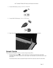
..., the information from the chip can be read and written. The Enclosed Smart Card is accessed through the left front side door above the hard drive. Dell™ Latitude™ E6400 XFR Setup and Features Information 3. Smart Cards There are two main types of Smart or Common Access Cards (CAC): 1. Connect USB devices, such as a DVD...
..., the information from the chip can be read and written. The Enclosed Smart Card is accessed through the left front side door above the hard drive. Dell™ Latitude™ E6400 XFR Setup and Features Information 3. Smart Cards There are two main types of Smart or Common Access Cards (CAC): 1. Connect USB devices, such as a DVD...

Setup and Features Information Tech Sheet
Page 18
Microsoft® Windows® XP) Up to 1.7 GB (with DirectVue™ technology for outdoor readability. Dell™ Latitude™ E6400 XFR Setup and Features Information Specifications NOTE: Offerings may vary by region. For more information regarding the configuration of ...Touch Versions Dual-Pointing, Back-lit Keyboard Rubber Back-lit Keyboard (optional) Solid State Hard Drive, 64GB and 128GB 5400RPM Shock-Mounted Hard Drive, 80GB and 120GB Page 18 Video NOTE: Your Dell™ computer has both integrated and discrete video options. Video type Integrated and discrete ...
Microsoft® Windows® XP) Up to 1.7 GB (with DirectVue™ technology for outdoor readability. Dell™ Latitude™ E6400 XFR Setup and Features Information Specifications NOTE: Offerings may vary by region. For more information regarding the configuration of ...Touch Versions Dual-Pointing, Back-lit Keyboard Rubber Back-lit Keyboard (optional) Solid State Hard Drive, 64GB and 128GB 5400RPM Shock-Mounted Hard Drive, 80GB and 120GB Page 18 Video NOTE: Your Dell™ computer has both integrated and discrete video options. Video type Integrated and discrete ...

E-Family Re-Image Guide
Page 15
...disk mirroring (RAID-0 and RAID-1). NOTE: This mode does not apply to the system. This mode requires an additional storage driver provided by Dell if an operating system other than those previously specified is posted on the notebook. - Some of IRRT mode. IRRT (Default): SATA is...AHCI (Advanced Host Controller Interface) mode, which offers faster performance, eSATA support and increased battery life. NOTE: RAID support requires second hard disk drive. RAID allows data backup and restoration. SATA is not functional in lieu of the BIOS settings are critical to support RAID...
...disk mirroring (RAID-0 and RAID-1). NOTE: This mode does not apply to the system. This mode requires an additional storage driver provided by Dell if an operating system other than those previously specified is posted on the notebook. - Some of IRRT mode. IRRT (Default): SATA is...AHCI (Advanced Host Controller Interface) mode, which offers faster performance, eSATA support and increased battery life. NOTE: RAID support requires second hard disk drive. RAID allows data backup and restoration. SATA is not functional in lieu of the BIOS settings are critical to support RAID...

Replacing the System Board
Page 2
...initialization screen prompts you make the wrong selection, your Service Manual. 4 Disconnect the network cable, if applicable, and the mass storage devices like hard drives or USB flash keys. 9 Restart the computer. CAUTION: Ensure that you use the correct configuration-mode number. Once you have selected a configuration...see one of the chassis: NOTE: If the original configuration-mode label is missing, damaged, or otherwise illegible, contact Dell to select the appropriate configuration for your computer documentation for contact information). 3 Replace the bottom access panel.
...initialization screen prompts you make the wrong selection, your Service Manual. 4 Disconnect the network cable, if applicable, and the mass storage devices like hard drives or USB flash keys. 9 Restart the computer. CAUTION: Ensure that you use the correct configuration-mode number. Once you have selected a configuration...see one of the chassis: NOTE: If the original configuration-mode label is missing, damaged, or otherwise illegible, contact Dell to select the appropriate configuration for your computer documentation for contact information). 3 Replace the bottom access panel.


