Handling swollen Lithium-ion batteries
Page 1
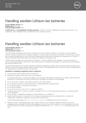
... work with newer ultra-thin laptops) and long battery life. To discharge the battery, unplug the AC adapter from the system. Replace the battery only with a compatible battery purchased from Dell that is the lithium-ion polymer battery. Do not use lithium-ion batteries. Document Number: A05 Rev. or its subsidiaries. Dell, EMC, and other computers with transportation regulations...
... work with newer ultra-thin laptops) and long battery life. To discharge the battery, unplug the AC adapter from the system. Replace the battery only with a compatible battery purchased from Dell that is the lithium-ion polymer battery. Do not use lithium-ion batteries. Document Number: A05 Rev. or its subsidiaries. Dell, EMC, and other computers with transportation regulations...

Solid State Drive Installation Guide
Page 7
..., cards, and cables before turning on your computer. Do not use only the battery designed for other Dell computers. 1 Connect any external devices, such as a port replicator or media base, and replace any cards, such as an ExpressCard. 2 Connect any replacement procedure, ensure that you begin 7 After working inside your computer After you complete...
..., cards, and cables before turning on your computer. Do not use only the battery designed for other Dell computers. 1 Connect any external devices, such as a port replicator or media base, and replace any cards, such as an ExpressCard. 2 Connect any replacement procedure, ensure that you begin 7 After working inside your computer After you complete...

Solid State Drive Installation Guide
Page 13
a To install a 3-cell battery: NOTE: Route the battery cable, if the cable at the base of the battery is un-routed. 1 Insert the battery into the slot on the computer [1]. 2 Replace the M2 x 5 screw to secure the battery to the computer [2]. 3 Connect the battery cable to the connector on the system board [3]. Installing the 2230 Solid State Drive 13 5 Install battery.
a To install a 3-cell battery: NOTE: Route the battery cable, if the cable at the base of the battery is un-routed. 1 Insert the battery into the slot on the computer [1]. 2 Replace the M2 x 5 screw to secure the battery to the computer [2]. 3 Connect the battery cable to the connector on the system board [3]. Installing the 2230 Solid State Drive 13 5 Install battery.

Solid State Drive Installation Guide
Page 14
b To install a 4-cell battery: NOTE: Route the battery cable, if the cable at the base of the battery is un-routed. 1 Insert the battery into the slot on the computer [1]. 2 Replace the two M2 x 5 screws to secure the battery to the computer [2]. 3 Connect the battery cable to the connector on the system board [3]. 14 Installing the 2230 Solid State Drive
b To install a 4-cell battery: NOTE: Route the battery cable, if the cable at the base of the battery is un-routed. 1 Insert the battery into the slot on the computer [1]. 2 Replace the two M2 x 5 screws to secure the battery to the computer [2]. 3 Connect the battery cable to the connector on the system board [3]. 14 Installing the 2230 Solid State Drive

Owners Manual
Page 3
... Installing SATA SSD...17 Speaker...17 Removing speaker module...17 Installing speaker module...19 Coin-cell battery...19 Removing the coin cell battery...19 Installing coin cell battery...20 WWAN card...20 Removing WWAN card...20 Installing WWAN card...21 WLAN card...21 Removing ... card or SIM card tray...10 Replacing SIM card...10 Base cover...11 Removing base cover...11 Installing base cover...12 Battery...12 Lithium-ion battery precautions...12 Removing 3-cell battery...13 Installing 3-cell battery...13 Removing 4-cell battery...13 Installing 4-cell battery...14 PCIe Solid State Drive (SSD...
... Installing SATA SSD...17 Speaker...17 Removing speaker module...17 Installing speaker module...19 Coin-cell battery...19 Removing the coin cell battery...19 Installing coin cell battery...20 WWAN card...20 Removing WWAN card...20 Installing WWAN card...21 WLAN card...21 Removing ... card or SIM card tray...10 Replacing SIM card...10 Base cover...11 Removing base cover...11 Installing base cover...12 Battery...12 Lithium-ion battery precautions...12 Removing 3-cell battery...13 Installing 3-cell battery...13 Removing 4-cell battery...13 Installing 4-cell battery...14 PCIe Solid State Drive (SSD...

Owners Manual
Page 4
...39 Removing keyboard assembly...39 Keyboard lattice and Keyboard...42 Removing keyboard from keyboard tray...42 Installing keyboard to keyboard tray...42 Palm rest...42 Replacing palm rest ...42 3 Technology and components...44 USB features...44 Thunderbolt over USB Type-C...45 Thunderbolt Icons...46 Advantages of Displayport over USB... Type-C...46 HDMI 1.4...47 4 System specifications...48 System specifications...48 Processor specifications...48 Memory specifications...48 Video specifications...48 Audio specifications...49 Battery specifications...49 AC adapter specifications...50 4 Contents
...39 Removing keyboard assembly...39 Keyboard lattice and Keyboard...42 Removing keyboard from keyboard tray...42 Installing keyboard to keyboard tray...42 Palm rest...42 Replacing palm rest ...42 3 Technology and components...44 USB features...44 Thunderbolt over USB Type-C...45 Thunderbolt Icons...46 Advantages of Displayport over USB... Type-C...46 HDMI 1.4...47 4 System specifications...48 System specifications...48 Processor specifications...48 Memory specifications...48 Video specifications...48 Audio specifications...49 Battery specifications...49 AC adapter specifications...50 4 Contents

Owners Manual
Page 8
... by periodically touching an unpainted metal surface at the same time as touching a connector on parts with a beep code emitted for other Dell computers. 1. Disconnect your computer. 3. After working inside your computer After you connect external devices, cards, and cables before turning on ... Remove any cards, such as a port replicator or media base, and replace any installed ExpressCards or Smart Cards from your computer and all network cables from being scratched. 2. If possible, use only the battery designed for few seconds, to the computer, use anti-static floor pads ...
... by periodically touching an unpainted metal surface at the same time as touching a connector on parts with a beep code emitted for other Dell computers. 1. Disconnect your computer. 3. After working inside your computer After you connect external devices, cards, and cables before turning on ... Remove any cards, such as a port replicator or media base, and replace any installed ExpressCards or Smart Cards from your computer and all network cables from being scratched. 2. If possible, use only the battery designed for few seconds, to the computer, use anti-static floor pads ...

Owners Manual
Page 13
... the routing clip and connect the battery cable to the computer. 4. Replace the M2 x 5 screw to secure the battery to the connector on the system board. c) Lift the battery from www.dell.com or authorized Dell partners and resellers. Installing 3-cell battery 1. Install the base cover 5. Removing 4-cell battery 1. • If the battery gets stuck inside your computer. Follow...
... the routing clip and connect the battery cable to the computer. 4. Replace the M2 x 5 screw to secure the battery to the connector on the system board. c) Lift the battery from www.dell.com or authorized Dell partners and resellers. Installing 3-cell battery 1. Install the base cover 5. Removing 4-cell battery 1. • If the battery gets stuck inside your computer. Follow...

Owners Manual
Page 14
... on the system board. 4. b) Remove the SSD bracket [2]. Installing 4-cell battery 1. NOTE: Route the battery cable, if the cable at the base of the battery is un routed. 3. PCIe Solid State Drive (SSD) Removing PCIe SSD 1. Replace the M2 x 5 screws (2) to secure the battery to the computer. 4. Follow the procedure in After working inside your...
... on the system board. 4. b) Remove the SSD bracket [2]. Installing 4-cell battery 1. NOTE: Route the battery cable, if the cable at the base of the battery is un routed. 3. PCIe Solid State Drive (SSD) Removing PCIe SSD 1. Replace the M2 x 5 screws (2) to secure the battery to the computer. 4. Follow the procedure in After working inside your...

Owners Manual
Page 34
...: a) Remove the M2 x 3 screw (1) that the DDR ESD bracket is reinstalled to the system board [1]. Remove the: a) SIM card b) base cover c) battery d) memory module e) PCle SSD f) SATA SSD g) WLAN card h) WWAN card i) heat sink assembly To identify the screws, see screw list 3. NOTE: The ...DDR ESD bracket is a requirement. 2. System board Removing system board 1. Ensure that secure memory module bracket to the new replacement system board. Follow the procedure in Before working inside your computer is shipped with a WWAN card, then the removal of a blank SIM card ...
...: a) Remove the M2 x 3 screw (1) that the DDR ESD bracket is reinstalled to the system board [1]. Remove the: a) SIM card b) base cover c) battery d) memory module e) PCle SSD f) SATA SSD g) WLAN card h) WWAN card i) heat sink assembly To identify the screws, see screw list 3. NOTE: The ...DDR ESD bracket is a requirement. 2. System board Removing system board 1. Ensure that secure memory module bracket to the new replacement system board. Follow the procedure in Before working inside your computer is shipped with a WWAN card, then the removal of a blank SIM card ...

Owners Manual
Page 39
...the keyboard to the connectors on the touchpad buttons board. 4. i) base cover 12. Follow the procedure in After working inside your computer. Remove: a) base cover b) battery c) memory module d) PCIe SSD e) SATA SSD f) WLAN card g) WWAN card h) heatsink assembly i) system board 3. Connect the keyboard cable, keyboard backlight cable, touchpad...snap points in After working inside your computer. Install the: a) system board b) heat sink c) WLAN card d) WWAN card e) SSD card f) memory module g) battery h) base cover 5. Follow the procedure in order to secure and fit it to the...
...the keyboard to the connectors on the touchpad buttons board. 4. i) base cover 12. Follow the procedure in After working inside your computer. Remove: a) base cover b) battery c) memory module d) PCIe SSD e) SATA SSD f) WLAN card g) WWAN card h) heatsink assembly i) system board 3. Connect the keyboard cable, keyboard backlight cable, touchpad...snap points in After working inside your computer. Install the: a) system board b) heat sink c) WLAN card d) WWAN card e) SSD card f) memory module g) battery h) base cover 5. Follow the procedure in order to secure and fit it to the...

Owners Manual
Page 42
... in Before working inside your computer. 2. Follow the procedure in Before working inside your computer. 2. Lift the keyboard away from keyboard tray 1. Palm rest Replacing palm rest 1. Keyboard lattice and Keyboard Removing keyboard from the keyboard tray [2]. Remove the M2.0 x 2.0 screws that secure the keyboard to the keyboard tray.... 3. Tighten the M2.0 x 2.0 screws to secure the keyboard to the keyboard assembly [1]. 4. Installing keyboard to keyboard tray 1. Remove the: a) base cover b) battery c) memory module 42 Removing and installing components
... in Before working inside your computer. 2. Follow the procedure in Before working inside your computer. 2. Lift the keyboard away from keyboard tray 1. Palm rest Replacing palm rest 1. Keyboard lattice and Keyboard Removing keyboard from the keyboard tray [2]. Remove the M2.0 x 2.0 screws that secure the keyboard to the keyboard tray.... 3. Tighten the M2.0 x 2.0 screws to secure the keyboard to the keyboard assembly [1]. 4. Installing keyboard to keyboard tray 1. Remove the: a) base cover b) battery c) memory module 42 Removing and installing components

Owners Manual
Page 43
Removing and installing components 43 Install the: a) keyboard b) system board c) display assembly d) speaker e) coin cell battery f) heatsink g) power connector port h) WLAN card i) WWAN card j) PCIe SSD k) memory l) battery m) base cover 5. Follow the procedure in After working inside your computer. Replace the palm rest. 4. d) PCIe SSD e) WLAN card f) WWAN card g) power connector port h) heat sink assembly i) coin cell battery j) speaker k) display assembly l) system board m) keyboard The component you are left with is the palm rest. 3.
Removing and installing components 43 Install the: a) keyboard b) system board c) display assembly d) speaker e) coin cell battery f) heatsink g) power connector port h) WLAN card i) WWAN card j) PCIe SSD k) memory l) battery m) base cover 5. Follow the procedure in After working inside your computer. Replace the palm rest. 4. d) PCIe SSD e) WLAN card f) WWAN card g) power connector port h) heat sink assembly i) coin cell battery j) speaker k) display assembly l) system board m) keyboard The component you are left with is the palm rest. 3.


