Owners Manual
Page 3
......20 Wireless module...20 Audio...21 Storage...21 Keyboard...22 Keyboard shortcuts of Latitude 7350...23 Camera...24 Clickpad...25 Clickpad with collaboration controls...25 Power adapter...26 Battery...27 Display...29 Fingerprint reader (optional)...30 Sensor ...30 GPU-Integrated...31 ...Multiple display support matrix...31 Hardware security...31 Smart-card reader...32 Contactless smart-card reader...32 Contacted smart-card reader...34 Operating and storage environment...35 Dell support policy...35 Dell...
......20 Wireless module...20 Audio...21 Storage...21 Keyboard...22 Keyboard shortcuts of Latitude 7350...23 Camera...24 Clickpad...25 Clickpad with collaboration controls...25 Power adapter...26 Battery...27 Display...29 Fingerprint reader (optional)...30 Sensor ...30 GPU-Integrated...31 ...Multiple display support matrix...31 Hardware security...31 Smart-card reader...32 Contactless smart-card reader...32 Contacted smart-card reader...34 Operating and storage environment...35 Dell support policy...35 Dell...

Owners Manual
Page 4
...sensitive components...40 After working inside your computer...40 BitLocker...40 Recommended tools...40 Screw list...41 Major components of Latitude 7350...42 Chapter 5: Removing and installing Customer Replaceable Units (CRUs 45 NanoSIM-card tray...45 Removing the nanoSIM-card...Replaceable Units (FRUs 61 Battery...61 Rechargeable Li-ion battery precautions...61 Removing the 3-cell battery ...61 Installing the 3-cell battery ...63 Removing the 4-cell battery ...64 Installing the 4-cell battery ...64 Battery cable...65 Removing the battery cable ...65 Installing the battery cable...66 Fan...67 ...
...sensitive components...40 After working inside your computer...40 BitLocker...40 Recommended tools...40 Screw list...41 Major components of Latitude 7350...42 Chapter 5: Removing and installing Customer Replaceable Units (CRUs 45 NanoSIM-card tray...45 Removing the nanoSIM-card...Replaceable Units (FRUs 61 Battery...61 Rechargeable Li-ion battery precautions...61 Removing the 3-cell battery ...61 Installing the 3-cell battery ...63 Removing the 4-cell battery ...64 Installing the 4-cell battery ...64 Battery cable...65 Removing the battery cable ...65 Installing the battery cable...66 Fan...67 ...
Owners Manual
Page 5
... existing system setup password 124 Clearing CMOS settings...125 Clearing BIOS (System Setup) and System passwords 125 Chapter 9: Troubleshooting...126 Handling swollen rechargeable Li-ion batteries...126 Contents 5
... existing system setup password 124 Clearing CMOS settings...125 Clearing BIOS (System Setup) and System passwords 125 Chapter 9: Troubleshooting...126 Handling swollen rechargeable Li-ion batteries...126 Contents 5
Owners Manual
Page 8
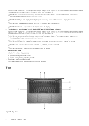
... light Indicates the battery-charge status. ● Solid yellow-Battery charge is low. ● Blinking yellow-Battery charge is required to connect a DisplayPort device. Smart-card reader slot (optional) Using smart card provides authentication in the Knowledge Base Resource at www.dell.com/support. NOTE: You can connect a Dell Docking Station to...for USB4 and Thunderbolt 4. Provides data transfer rates of up to an external display using a display adapter. Provides data transfer rates of Latitude 7350 NOTE: Thunderbolt 4 supports two 4K displays or one 8K display. 4.
... light Indicates the battery-charge status. ● Solid yellow-Battery charge is low. ● Blinking yellow-Battery charge is required to connect a DisplayPort device. Smart-card reader slot (optional) Using smart card provides authentication in the Knowledge Base Resource at www.dell.com/support. NOTE: You can connect a Dell Docking Station to...for USB4 and Thunderbolt 4. Provides data transfer rates of up to an external display using a display adapter. Provides data transfer rates of Latitude 7350 NOTE: Thunderbolt 4 supports two 4K displays or one 8K display. 4.

Owners Manual
Page 15
.... ● S5 (OFF) - S5 AC Adapter Solid White S0 - Tent mode Battery charge and status light The following table lists the battery charge and status light behavior of Latitude 7350 15 S5 Battery Off S0 - S5 Battery Charge Level Fully Charged < Fully Charged 11-100% < 10% ● S0 (ON...) - The context data is turned on. ● S4 (Hibernate) - Battery charge and status light ...
.... ● S5 (OFF) - S5 AC Adapter Solid White S0 - Tent mode Battery charge and status light The following table lists the battery charge and status light behavior of Latitude 7350 15 S5 Battery Off S0 - S5 Battery Charge Level Fully Charged < Fully Charged 11-100% < 10% ● S0 (ON...) - The context data is turned on. ● S4 (Hibernate) - Battery charge and status light ...
Owners Manual
Page 16
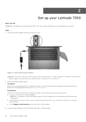
... up your Latitude 7350 About this task NOTE: The images in this document may go into power-saving mode during shipment to conserve charge on the battery. When setting up your contact details. 3. Connecting the power adapter NOTE: The battery may differ from the Windows Start menu-Recommended. 16 Set up , Dell recommends that the...
... up your Latitude 7350 About this task NOTE: The images in this document may go into power-saving mode during shipment to conserve charge on the battery. When setting up your contact details. 3. Connecting the power adapter NOTE: The battery may differ from the Windows Start menu-Recommended. 16 Set up , Dell recommends that the...

Owners Manual
Page 24
... Camera ● 5MP RGB-IR Camera location Front camera Camera sensor type Ambient light sensor Camera resolution: Still image 2.07 megapixel 24 Specifications of your Latitude 7350. Table 14. Table 15. Secondary behavior (continued) Keys Fn + F3 Fn + F4 Fn + F5 Fn + F6 Fn + F8 Fn + F9 Fn ... on wireless Pause or Break Sleep Toggle scroll lock Toggle between power and battery-status light or hard drive activity light System request Open the application menu Toggle Fn-key lock Page up Page down Home End Camera The following table lists the camera specifications of Latitude 7350
... Camera ● 5MP RGB-IR Camera location Front camera Camera sensor type Ambient light sensor Camera resolution: Still image 2.07 megapixel 24 Specifications of your Latitude 7350. Table 14. Table 15. Secondary behavior (continued) Keys Fn + F3 Fn + F4 Fn + F5 Fn + F6 Fn + F8 Fn + F9 Fn ... on wireless Pause or Break Sleep Toggle scroll lock Toggle between power and battery-status light or hard drive activity light System request Open the application menu Toggle Fn-key lock Page up Page down Home End Camera The following table lists the camera specifications of Latitude 7350

Owners Manual
Page 27
... temperature ranges may differ among components, so operating or storing the device outside these ranges may impact the performance of your Latitude 7350. Table 19. Power adapter specifications (continued) Description Option one Battery type 2-cell, 38 Wh, lithium ion, ExpressCharge Option two 3-cell, 57 Wh, lithium ion, ExpressCharge Option three Option four 2-cell... A 5.00 A 20.00 VDC 0°C to 40°C (32°F to 104°F) -40°C to 70°C (-40°F to 158°F) Specifications of Latitude 7350 27 Table 18.
... temperature ranges may differ among components, so operating or storing the device outside these ranges may impact the performance of your Latitude 7350. Table 19. Power adapter specifications (continued) Description Option one Battery type 2-cell, 38 Wh, lithium ion, ExpressCharge Option two 3-cell, 57 Wh, lithium ion, ExpressCharge Option three Option four 2-cell... A 5.00 A 20.00 VDC 0°C to 40°C (32°F to 104°F) -40°C to 70°C (-40°F to 158°F) Specifications of Latitude 7350 27 Table 18.
Owners Manual
Page 28
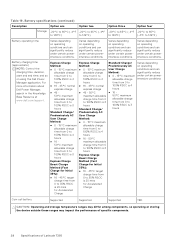
... temperature ranges may differ among components, so operating or storing the device outside these ranges may impact the performance of specific components. 28 Specifications of Latitude 7350 Battery specifications (continued) Description Option one Storage -20°C to 65°C (-4°F to 149°F) Option two -20°C to 65°C ... powerintensive conditions. Varies depending on operating conditions and can significantly reduce under certain powerintensive conditions. Table 19. For more information about Dell Power Manager, search in the Knowledge Base Resource at www...
... temperature ranges may differ among components, so operating or storing the device outside these ranges may impact the performance of specific components. 28 Specifications of Latitude 7350 Battery specifications (continued) Description Option one Storage -20°C to 65°C (-4°F to 149°F) Option two -20°C to 65°C ... powerintensive conditions. Varies depending on operating conditions and can significantly reduce under certain powerintensive conditions. Table 19. For more information about Dell Power Manager, search in the Knowledge Base Resource at www...
Owners Manual
Page 29
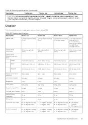
... Option one Option two Option three Option four CAUTION: Dell recommends that you charge the battery regularly for optimal power consumption. If your battery charge is completely depleted, connect the power adapter, turn on your computer, and then restart your Latitude 7350. Table 20. Table 19. Battery specifications (continued) Description Option one Display type Full High...
... Option one Option two Option three Option four CAUTION: Dell recommends that you charge the battery regularly for optimal power consumption. If your battery charge is completely depleted, connect the power adapter, turn on your computer, and then restart your Latitude 7350. Table 20. Table 19. Battery specifications (continued) Description Option one Display type Full High...
Owners Manual
Page 36
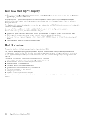
... performance, and user experience through computer usage analysis and learning ● Faster application launch and seamless application transition ● Intelligent battery run-time extension ● Optimized Audio for best meeting experience ● Locks computer when walks away for enhanced security ●... is a color in the light spectrum which has a short wavelength and high energy. On Latitude 7350 with TÜV Rheinland's requirement for 20 minutes every two hours. Dell low blue light display WARNING: Prolonged exposure to blue light from the display may disrupt sleep ...
... performance, and user experience through computer usage analysis and learning ● Faster application launch and seamless application transition ● Intelligent battery run-time extension ● Optimized Audio for best meeting experience ● Locks computer when walks away for enhanced security ●... is a color in the light spectrum which has a short wavelength and high energy. On Latitude 7350 with TÜV Rheinland's requirement for 20 minutes every two hours. Dell low blue light display WARNING: Prolonged exposure to blue light from the display may disrupt sleep ...

Owners Manual
Page 37
... and repairs as the metal at the back of the computer. CAUTION: Exercise caution when handling rechargeable Li-ion batteries in this document. Swollen batteries should not be replaced and disposed properly. NOTE: The color of your computer from all open applications. 2. Shut... replace all covers, panels, and screws before disconnecting the cable. After you have connectors with the product or at www.dell.com/ regulatory_compliance. Damage due to avoid bending the connector pins. Before working inside your computer from your personal safety. Disconnect...
... and repairs as the metal at the back of the computer. CAUTION: Exercise caution when handling rechargeable Li-ion batteries in this document. Swollen batteries should not be replaced and disposed properly. NOTE: The color of your computer from all open applications. 2. Shut... replace all covers, panels, and screws before disconnecting the cable. After you have connectors with the product or at www.dell.com/ regulatory_compliance. Damage due to avoid bending the connector pins. Before working inside your computer from your personal safety. Disconnect...

Owners Manual
Page 38
.... a. Press any installation or break or fix procedures involving disassembly or reassembly: ● Turn off power, without disconnecting the battery cable from the system board before conducting repairs in full contact with your computer or unable to turn on your computer, if ...your skin, and ensure that incorporate standby power are powered while turned off. To disconnect the battery cable, follow the steps in the system board. d. Standby power Dell products with non-conductive rubber soles to avoid electrostatic discharge (ESD) damage. ● After removing...
.... a. Press any installation or break or fix procedures involving disassembly or reassembly: ● Turn off power, without disconnecting the battery cable from the system board before conducting repairs in full contact with your computer or unable to turn on your computer, if ...your skin, and ensure that incorporate standby power are powered while turned off. To disconnect the battery cable, follow the steps in the system board. d. Standby power Dell products with non-conductive rubber soles to avoid electrostatic discharge (ESD) damage. ● After removing...

Owners Manual
Page 41
... replacing a component. Screw list Component Base cover Screw type Captive screw Quantity 8 Screw image M.2 SSD shielding cover M2x3 1 Solid-state drive M2x4 1 WWAN bracket 3-cell battery 4-cell battery Fan M2x3 1 Captive screw 1 M2x4 4 Captive screw 1 M2x4 4 M2x4 1 Heat-sink 5G WLAN bracket Captive screw 4 M2x3 1 WLAN-antenna module bracket M2x3 4 EDP-cable...
... replacing a component. Screw list Component Base cover Screw type Captive screw Quantity 8 Screw image M.2 SSD shielding cover M2x3 1 Solid-state drive M2x4 1 WWAN bracket 3-cell battery 4-cell battery Fan M2x3 1 Captive screw 1 M2x4 4 Captive screw 1 M2x4 4 M2x4 1 Heat-sink 5G WLAN bracket Captive screw 4 M2x3 1 WLAN-antenna module bracket M2x3 4 EDP-cable...

Owners Manual
Page 44
... purchased by the customer. Speaker 12. Palm-rest and keyboard assembly 13. Keyboard bracket 9. Fingerprint reader NOTE: Dell provides a list of components and their part numbers for purchase options. 44 Working inside your Dell sales representative for the original system configuration purchased. Heat sink 6. WWAN-card shield 18. Contact your computer WWAN...
... purchased by the customer. Speaker 12. Palm-rest and keyboard assembly 13. Keyboard bracket 9. Fingerprint reader NOTE: Dell provides a list of components and their part numbers for purchase options. 44 Working inside your Dell sales representative for the original system configuration purchased. Heat sink 6. WWAN-card shield 18. Contact your computer WWAN...

Owners Manual
Page 58
... the base cover. 2. It is recommended that you are replacing a component, remove the existing component before removing the coin-cell battery. 58 Removing and installing Customer Replaceable Units (CRUs) Installing the speakers for mainstream Prerequisites If you note the BIOS setup program's ...visual representation of the palm-rest and keyboard assembly. Follow the procedure in Before working inside your computer. Coin-cell battery Removing the coin-cell battery Prerequisites 1. Figure 26. Next steps 1. Then secure the speaker cable into the slots on the palm-rest and ...
... the base cover. 2. It is recommended that you are replacing a component, remove the existing component before removing the coin-cell battery. 58 Removing and installing Customer Replaceable Units (CRUs) Installing the speakers for mainstream Prerequisites If you note the BIOS setup program's ...visual representation of the palm-rest and keyboard assembly. Follow the procedure in Before working inside your computer. Coin-cell battery Removing the coin-cell battery Prerequisites 1. Figure 26. Next steps 1. Then secure the speaker cable into the slots on the palm-rest and ...

Owners Manual
Page 59
...Removing and installing Customer Replaceable Units (CRUs) 59 2. Unroute the coin-cell battery cable from the connector on the system board. 3. Removing the coin-cell battery Steps 1. Installing the coin-cell battery CAUTION: The information in this task The following image indicates the location of the... coin-cell battery and provides a visual representation of the installation procedure. Using a plastic scribe, pry the coin-cell battery off its slot on the system board. About this task The following image...
...Removing and installing Customer Replaceable Units (CRUs) 59 2. Unroute the coin-cell battery cable from the connector on the system board. 3. Removing the coin-cell battery Steps 1. Installing the coin-cell battery CAUTION: The information in this task The following image indicates the location of the... coin-cell battery and provides a visual representation of the installation procedure. Using a plastic scribe, pry the coin-cell battery off its slot on the system board. About this task The following image...

Owners Manual
Page 60
Route the coin-cell battery cable back to the connector on the system board. 3. Connect the coin-cell battery cable to the routing guides on the system board. Install the base cover. 2. Follow the procedure in After working inside your computer. 60 Removing and installing Customer Replaceable Units (CRUs) Place the coin-cell battery into its slot on the system board. 2. Next steps 1. Installing the coin-cell battery Steps 1. Figure 28.
Route the coin-cell battery cable back to the connector on the system board. 3. Connect the coin-cell battery cable to the routing guides on the system board. Install the base cover. 2. Follow the procedure in After working inside your computer. 60 Removing and installing Customer Replaceable Units (CRUs) Place the coin-cell battery into its slot on the system board. 2. Next steps 1. Installing the coin-cell battery Steps 1. Figure 28.

Owners Manual
Page 61
... as puncturing, bending, or crushing a rechargeable Li-ion battery can be dangerous. See www.dell.com/contactdell. ● Always purchase genuine batteries from www.dell.com or authorized Dell partners and resellers. ● Swollen batteries should not be used and should be conducted by Dell Technologies. Removing the 3-cell battery CAUTION: The information in this chapter are not...
... as puncturing, bending, or crushing a rechargeable Li-ion battery can be dangerous. See www.dell.com/contactdell. ● Always purchase genuine batteries from www.dell.com or authorized Dell partners and resellers. ● Swollen batteries should not be used and should be conducted by Dell Technologies. Removing the 3-cell battery CAUTION: The information in this chapter are not...

Owners Manual
Page 62
...tab to the palm-rest and keyboard assembly. 4. Disconnect the battery cable from the 3-cell battery. 62 Removing and installing Field Replaceable Units (FRUs) Figure 29. Lift the 3-cell battery along with the battery cable off the palm-rest and keyboard assembly. 5. Loosen the ...captive screw that secure the 3-cell battery to disconnect the battery cable from the connector on the 3-cell battery. 6. Carefully push the battery filler downwards to the palm-rest and keyboard assembly. 3. Prerequisites 1. Follow the procedure in...
...tab to the palm-rest and keyboard assembly. 4. Disconnect the battery cable from the 3-cell battery. 62 Removing and installing Field Replaceable Units (FRUs) Figure 29. Lift the 3-cell battery along with the battery cable off the palm-rest and keyboard assembly. 5. Loosen the ...captive screw that secure the 3-cell battery to disconnect the battery cable from the connector on the 3-cell battery. 6. Carefully push the battery filler downwards to the palm-rest and keyboard assembly. 3. Prerequisites 1. Follow the procedure in...


