

Service Manual
Page 1
Dell™ Inspiron™ 410 Service Manual Technical Overview Before You Begin Top Cover Bottom Cover I/O Bezel Top Bracket I/O Bracket Optical Drive Drive Bay Power-Button Bracket Coin-Cell Battery Infrared Board Hard Drive Wireless Mini-Card Memory Module(s) Processor Heat Sink Processor Chassis Fan Graphics Card System Board System Setup Utility Notes, Cautions, and Warnings NOTE...
Dell™ Inspiron™ 410 Service Manual Technical Overview Before You Begin Top Cover Bottom Cover I/O Bezel Top Bracket I/O Bracket Optical Drive Drive Bay Power-Button Bracket Coin-Cell Battery Infrared Board Hard Drive Wireless Mini-Card Memory Module(s) Processor Heat Sink Processor Chassis Fan Graphics Card System Board System Setup Utility Notes, Cautions, and Warnings NOTE...

Service Manual
Page 10
...Remove the two screws that secure the graphics card to the system-board connector. 5. Insert the graphics card at www.dell.com/regulatory_compliance. For additional safety best ...graphics card from the system board connector. 1 graphics card 2 screws (2) Replacing the Graphics Card 1. Removing the Graphics Card 1. Press the other end of the graphics card down and replace the two screws that secure the graphics card to the system board. 4. Back to Contents Page Graphics Card Dell™ Inspiron™ 410 Service Manual Removing the Graphics Card Replacing the Graphics Card...
...Remove the two screws that secure the graphics card to the system-board connector. 5. Insert the graphics card at www.dell.com/regulatory_compliance. For additional safety best ...graphics card from the system board connector. 1 graphics card 2 screws (2) Replacing the Graphics Card 1. Removing the Graphics Card 1. Press the other end of the graphics card down and replace the two screws that secure the graphics card to the system board. 4. Back to Contents Page Graphics Card Dell™ Inspiron™ 410 Service Manual Removing the Graphics Card Replacing the Graphics Card...

Service Manual
Page 32
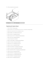
...on the computer. Disconnect all the cables connected to release the connectors on the system board from the slots on your warranty. Remove the graphics card (see Removing the Top Bracket). 4. Removing the System Board 1. Damage due to servicing that secure the system board to the chassis. 20...on the chassis. Remove the Mini-Card (see Removing the Mini-Card). 15. Slide the system board to the back of the cable routing before disconnecting the cables from the chassis. 21. Back to Contents Page System Board Dell™ Inspiron™ 410 Service Manual Removing the System Board ...
...on the computer. Disconnect all the cables connected to release the connectors on the system board from the slots on your warranty. Remove the graphics card (see Removing the Top Bracket). 4. Removing the System Board 1. Damage due to servicing that secure the system board to the chassis. 20...on the chassis. Remove the Mini-Card (see Removing the Mini-Card). 15. Slide the system board to the back of the cable routing before disconnecting the cables from the chassis. 21. Back to Contents Page System Board Dell™ Inspiron™ 410 Service Manual Removing the System Board ...
Service Manual
Page 33
...). 15. Replace the four screws that secure the system board to the system board. 9. Replace the Mini-Card (see Replacing the Power-Button Bracket). 16. Replace the power-button bracket (see Replacing the Mini-Card). 8. Lift the system board away from the computer. 1 screws (4) 2 system board Replacing the System Board 1. ...fan (see Replacing the Bottom Cover). 19. Replace the bottom cover (see Replacing the Chassis Fan). 12. Replace the top bracket (see Replacing the Graphics Card). 5. 22. Follow the procedures in place. 3. Connect all the cables to the chassis. 4. Replace the...
...). 15. Replace the four screws that secure the system board to the system board. 9. Replace the Mini-Card (see Replacing the Power-Button Bracket). 16. Replace the power-button bracket (see Replacing the Mini-Card). 8. Lift the system board away from the computer. 1 screws (4) 2 system board Replacing the System Board 1. ...fan (see Replacing the Bottom Cover). 19. Replace the bottom cover (see Replacing the Chassis Fan). 12. Replace the top bracket (see Replacing the Graphics Card). 5. 22. Follow the procedures in place. 3. Connect all the cables to the chassis. 4. Replace the...

Setup Guide
Page 71
Input voltage 100-240 VAC Input current 1.5 A Input frequency 50-60 Hz Output power 75 W Output current 3.95A Rated output voltage 19 +/- 0.95 VDC Dimensions: Height 30.3 mm (1.19 inches) Width 57 mm (2.24 inches) Depth 132.5 mm (5.21 inches) Weight (with the optional graphics card. Basic Specifications Computer Model Inspiron 300 Inspiron 400 AC Adapter (75W) NOTE: The 75W AC adapter is shipped with cables) 0.45 kg (0.99 lbs) Weight (Auto-Air adapter without AC/DC cord) 0.46 kg (1.01 lbs) 69
Input voltage 100-240 VAC Input current 1.5 A Input frequency 50-60 Hz Output power 75 W Output current 3.95A Rated output voltage 19 +/- 0.95 VDC Dimensions: Height 30.3 mm (1.19 inches) Width 57 mm (2.24 inches) Depth 132.5 mm (5.21 inches) Weight (with the optional graphics card. Basic Specifications Computer Model Inspiron 300 Inspiron 400 AC Adapter (75W) NOTE: The 75W AC adapter is shipped with cables) 0.45 kg (0.99 lbs) Weight (Auto-Air adapter without AC/DC cord) 0.46 kg (1.01 lbs) 69


