Service Manual
Page 3
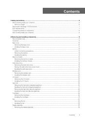
... list...9 Base cover...10 Removing the base cover...10 Installing the base cover...11 Battery...13 Lithium-ion battery precautions...13 Removing the battery...13 Installing the battery...14 Memory module...16 Removing the memory module...16 Installing the memory module...17 Solid-state drive...18 Removing the solid-state drive...18 Moving the solid-state drive screw mount...19 Installing the solid-state drive...20 Wireless card...22 Removing the wireless card...22 Installing the wireless card...23 I/O board...25 Removing the I/O board...25 Installing the I/O board...25...
... list...9 Base cover...10 Removing the base cover...10 Installing the base cover...11 Battery...13 Lithium-ion battery precautions...13 Removing the battery...13 Installing the battery...14 Memory module...16 Removing the memory module...16 Installing the memory module...17 Solid-state drive...18 Removing the solid-state drive...18 Moving the solid-state drive screw mount...19 Installing the solid-state drive...20 Wireless card...22 Removing the wireless card...22 Installing the wireless card...23 I/O board...25 Removing the I/O board...25 Installing the I/O board...25...
Service Manual
Page 4
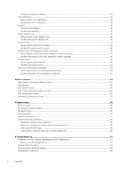
... Wireless and Bluetooth drivers...55 4 System setup...56 BIOS overview...56 Entering BIOS setup program...56 Navigation keys...56 Boot Sequence...57 System setup options...57 System and setup password...64 Assigning a system setup password...65 Deleting or changing an existing system setup password 65 Clearing CMOS settings...66 Clearing BIOS (System Setup) and System passwords 66 5 Troubleshooting...67 Enhanced Pre-Boot System Assessment (ePSA) diagnostics 67 Running the ePSA diagnostics...67 System diagnostic lights...67 Recovering the operating system...68 Flashing BIOS (USB key...
... Wireless and Bluetooth drivers...55 4 System setup...56 BIOS overview...56 Entering BIOS setup program...56 Navigation keys...56 Boot Sequence...57 System setup options...57 System and setup password...64 Assigning a system setup password...65 Deleting or changing an existing system setup password 65 Clearing CMOS settings...66 Clearing BIOS (System Setup) and System passwords 66 5 Troubleshooting...67 Enhanced Pre-Boot System Assessment (ePSA) diagnostics 67 Running the ePSA diagnostics...67 System diagnostic lights...67 Recovering the operating system...68 Flashing BIOS (USB key...
Service Manual
Page 7
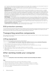
... wire can be connected to the mat and to any media card and optical disc from your hand, on parts with a beep code emitted for shut-down instructions. 3. If you do not provide adequate protection. As the industry pushes for doing this reason, some previously approved methods of handling parts are no longer allowed; Each Field Service kit includes...
... wire can be connected to the mat and to any media card and optical disc from your hand, on parts with a beep code emitted for shut-down instructions. 3. If you do not provide adequate protection. As the industry pushes for doing this reason, some previously approved methods of handling parts are no longer allowed; Each Field Service kit includes...
Service Manual
Page 8
... when servicing Dell products. Connect any external devices, peripherals, or cables you removed before working on your body and back. 6. one. Always look for a large open flat work surface, and parts should be returned to Dell, it is different than 50 pounds. When transporting ESD sensitive components such as replacement parts or parts to be folded over and taped shut and all field service technicians use the...
... when servicing Dell products. Connect any external devices, peripherals, or cables you removed before working on your body and back. 6. one. Always look for a large open flat work surface, and parts should be returned to Dell, it is different than 50 pounds. When transporting ESD sensitive components such as replacement parts or parts to be folded over and taped shut and all field service technicians use the...
Service Manual
Page 17
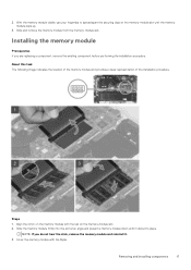
With the memory module visible, use your fingertips to spread apart the securing clips on the memory-module slot until it . 3. About this task The following image indicates the location of the memory module and provides a visual representation of the installation procedure. Cover the memory module with the tab on the memory module with the Mylar. Slide and remove the memory module from the memory-module slot. NOTE: If you are replacing a component, remove the existing...
With the memory module visible, use your fingertips to spread apart the securing clips on the memory-module slot until it . 3. About this task The following image indicates the location of the memory module and provides a visual representation of the installation procedure. Cover the memory module with the tab on the memory module with the Mylar. Slide and remove the memory module from the memory-module slot. NOTE: If you are replacing a component, remove the existing...
Service Manual
Page 50
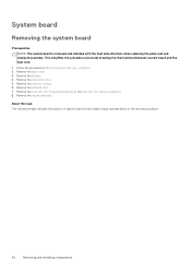
Remove the wireless card. 7. Follow the procedure in Before working inside your computer. 2. About this task The following image indicates the location of system board and provides a visual representation of the removal procedure. 50 Removing and installing components Remove the base cover. 3. Remove the memory module. 6. Remove the heat sink (for integrated graphics) or the heat sink (for discrete graphics). 8. Remove the display assembly. Remove the battery. 4. System board Removing the system board Prerequisites...
Remove the wireless card. 7. Follow the procedure in Before working inside your computer. 2. About this task The following image indicates the location of system board and provides a visual representation of the removal procedure. 50 Removing and installing components Remove the base cover. 3. Remove the memory module. 6. Remove the heat sink (for integrated graphics) or the heat sink (for discrete graphics). 8. Remove the display assembly. Remove the battery. 4. System board Removing the system board Prerequisites...
Service Manual
Page 53
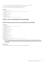
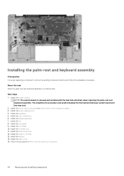
... inside your computer. 2. Remove the memory module. 5. Connect the power-adapter port cable to the connectors on the system board. 5. Install the heat sink (for integrated graphics) or the heat sink (for discrete graphics). 3. Install the battery. 7. Palm-rest and keyboard assembly Removing the palm-rest and keyboard assembly Prerequisites 1. Remove the touchpad. 9. Remove the display assembly. 11. Install the wireless card. 4. Removing and installing components 53 Remove the base cover. 3. Remove the system board. Install the memory module. 5. Follow the...
... inside your computer. 2. Remove the memory module. 5. Connect the power-adapter port cable to the connectors on the system board. 5. Install the heat sink (for integrated graphics) or the heat sink (for discrete graphics). 3. Install the battery. 7. Palm-rest and keyboard assembly Removing the palm-rest and keyboard assembly Prerequisites 1. Remove the touchpad. 9. Remove the display assembly. 11. Install the wireless card. 4. Removing and installing components 53 Remove the base cover. 3. Remove the system board. Install the memory module. 5. Follow the...
Service Manual
Page 54
... system board and the heat sink. 2. Install the speakers. 5. Install the solid-state drive. 12. Install the memory module. 13. Install the battery. 14. Install the system board. Install the fan. 8. NOTE: The system board is removed and installed with fingerprint reader. 3. Install the power-adapter port. 4. Install the I/O board. 10. Follow the procedure in After working inside your computer. 54 Removing and installing components Installing the palm-rest and keyboard assembly Prerequisites If you are replacing a component, remove the...
... system board and the heat sink. 2. Install the speakers. 5. Install the solid-state drive. 12. Install the memory module. 13. Install the battery. 14. Install the system board. Install the fan. 8. NOTE: The system board is removed and installed with fingerprint reader. 3. Install the power-adapter port. 4. Install the I/O board. 10. Follow the procedure in After working inside your computer. 54 Removing and installing components Installing the palm-rest and keyboard assembly Prerequisites If you are replacing a component, remove the...
Service Manual
Page 55
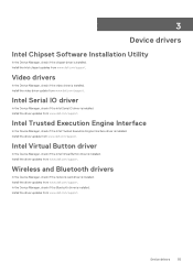
... Interface In the Device Manager, check if the Intel Trusted Execution Engine Interface driver is installed. Install the driver updates from www.dell.com/support. Device drivers 55 Install the driver updates from www.dell.com/support. Wireless and Bluetooth drivers In the Device Manager, check if the network card driver is installed. Install the video driver update from www.dell.com/support. Video drivers In the Device Manager, check if the video driver is installed. Install the driver update from www.dell.com/support. Intel Serial IO driver In the Device Manager, check if the...
... Interface In the Device Manager, check if the Intel Trusted Execution Engine Interface driver is installed. Install the driver updates from www.dell.com/support. Device drivers 55 Install the driver updates from www.dell.com/support. Wireless and Bluetooth drivers In the Device Manager, check if the network card driver is installed. Install the video driver update from www.dell.com/support. Video drivers In the Device Manager, check if the video driver is installed. Install the driver update from www.dell.com/support. Intel Serial IO driver In the Device Manager, check if the...
Service Manual
Page 56
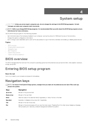
...; Navigation keys • Boot Sequence • System setup options • System and setup password BIOS overview The BIOS manages data flow between the computer's operating system and attached devices such as the user password, type of hard drive installed, and enabling or disabling base devices. Moves to the previous page until you restart the system. Certain changes can make are an expert computer user, do not take effect until you view the main screen...
...; Navigation keys • Boot Sequence • System setup options • System and setup password BIOS overview The BIOS manages data flow between the computer's operating system and attached devices such as the user password, type of hard drive installed, and enabling or disabling base devices. Moves to the previous page until you restart the system. Certain changes can make are an expert computer user, do not take effect until you view the main screen...
Service Manual
Page 57
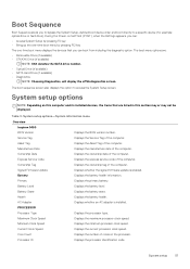
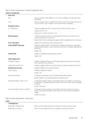
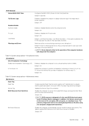
... the System Setup-defined boot device order and boot directly to access the System Setup screen. System setup options-System information menu Overview Inspiron 5490 BIOS Version Displays the BIOS version number. Ownership Tag Displays the ownership tag of the computer. PROCESSOR Processor Type Displays the processor type. System setup 57 Asset Tag Displays the Asset Tag of the computer. Express Service Code Displays the express service code of the computer. Health Displays the battery health. The boot menu options are listed in this...
... the System Setup-defined boot device order and boot directly to access the System Setup screen. System setup options-System information menu Overview Inspiron 5490 BIOS Version Displays the BIOS version number. Ownership Tag Displays the ownership tag of the computer. PROCESSOR Processor Type Displays the processor type. System setup 57 Asset Tag Displays the Asset Tag of the computer. Express Service Code Displays the express service code of the computer. Health Displays the battery health. The boot menu options are listed in this...
Service Manual
Page 59
... drives. Default: ON USB Configuration Enable Boot Support Enable External USB Ports Miscellaneous Devices Enable Camera Enables or disables booting from USB mass storage devices such as external hard drive, optical drive, and USB drive. Default: Disabled. The keyboard backlight timeout value is only effect when the backlight is configured to the date take effect immediately. Table 5. Default: ON Keyboard Illumination Configures the operating mode of various onboard drives. System setup options-Video menu Video LCD Brightness Brightness on battery power Sets the screen brightness...
... drives. Default: ON USB Configuration Enable Boot Support Enable External USB Ports Miscellaneous Devices Enable Camera Enables or disables booting from USB mass storage devices such as external hard drive, optical drive, and USB drive. Default: Disabled. The keyboard backlight timeout value is only effect when the backlight is configured to the date take effect immediately. Table 5. Default: ON Keyboard Illumination Configures the operating mode of various onboard drives. System setup options-Video menu Video LCD Brightness Brightness on battery power Sets the screen brightness...
Service Manual
Page 60
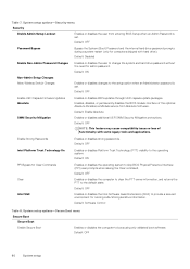
...-Admin Password Changes Enables or disables the user to change the system and hard drive password without the need for Clear Commands Enables or disables the operating system to boos using only validated boot software. Enables, disables, or permanently disables the BIOS module interface of functionality with hard drive). Default: OFF NOTE: This feature may cause compatibility issues or loss of the optional Absolute Persistence Module service from entering BIOS Setup when an Admin Password is set . Default: OFF Clear Enables or disables the computer to clear the PTT owner...
...-Admin Password Changes Enables or disables the user to change the system and hard drive password without the need for Clear Commands Enables or disables the operating system to boos using only validated boot software. Enables, disables, or permanently disables the BIOS module interface of functionality with hard drive). Default: OFF NOTE: This feature may cause compatibility issues or loss of the optional Absolute Persistence Module service from entering BIOS Setup when an Admin Password is set . Default: OFF Clear Enables or disables the computer to clear the PTT owner...
Service Manual
Page 62
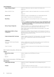
... work day. Enables Advanced Battery Charge Configuration from Standby mode. Default: OFF Enables or disables Intel Speed Shift Technology support which enables the operating system to display adapter warning messages during power usage hours. Default: ON Fastboot Configures the speed of each day. Default: OFF Enables the computer to run on battery during boot. Enables the computer to wake from the off state whenever the lid is connected to a Dell USB-C dock. Default: Adaptive. System setup options-POST Behavior menu...
... work day. Enables Advanced Battery Charge Configuration from Standby mode. Default: OFF Enables or disables Intel Speed Shift Technology support which enables the operating system to display adapter warning messages during power usage hours. Default: ON Fastboot Configures the speed of each day. Default: OFF Enables the computer to run on battery during boot. Enables the computer to wake from the off state whenever the lid is connected to a Dell USB-C dock. Default: Adaptive. System setup options-POST Behavior menu...
Service Manual
Page 63
... BIOS Recovery from Hard Drive Enables the computer to display full screen logo if the image match screen resolution. POST Behavior Extend BIOS POST Time Full Screen Logo Numlock Enable Numlock Enable Fn Lock Lock Mode Warnings and Errors Configures the BIOS POST (Power-On Self-Test) load time. Default: OFF Enables or disables Numlock when the computer boots. Selects an action on Warnings and Errors. Default: Prompt on encountering a warning or error during boot. System setup options-Virtualization menu...
... BIOS Recovery from Hard Drive Enables the computer to display full screen logo if the image match screen resolution. POST Behavior Extend BIOS POST Time Full Screen Logo Numlock Enable Numlock Enable Fn Lock Lock Mode Warnings and Errors Configures the BIOS POST (Power-On Self-Test) load time. Default: OFF Enables or disables Numlock when the computer boots. Selects an action on Warnings and Errors. Default: Prompt on encountering a warning or error during boot. System setup options-Virtualization menu...
Service Manual
Page 64
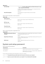
... Recovery Enables or disables the boot flow for the data on the next reboot. Maintenance Start Data Wipe Allow BIOS Downgrade CAUTION: This Secure Wipe Operation will queue up a data wipe cycle for Dell operating system Recovery tool. Default: ON BIOSConnect Enables or disables attempting cloud Service OS recovery. System and setup password Password type System password Setup password Description Password that you must enter to access and make changes to the motherboard on your system. CAUTION: Anyone can create a system password...
... Recovery Enables or disables the boot flow for the data on the next reboot. Maintenance Start Data Wipe Allow BIOS Downgrade CAUTION: This Secure Wipe Operation will queue up a data wipe cycle for Dell operating system Recovery tool. Default: ON BIOSConnect Enables or disables attempting cloud Service OS recovery. System and setup password Password type System password Setup password Description Password that you must enter to access and make changes to the motherboard on your system. CAUTION: Anyone can create a system password...
Service Manual
Page 65
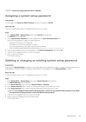
... changes and exit from System Setup. The computer reboot. NOTE: System and setup password feature is displayed. 2. The Security screen is Unlocked (in Not Set. Deleting or changing an existing system setup password Prerequisites Ensure that the Password Status is displayed. 2. In the System BIOS or System Setup screen, select System Security and press Enter. In the System BIOS or System Setup screen, select Security and press Enter. Press Y to delete or change...
... changes and exit from System Setup. The computer reboot. NOTE: System and setup password feature is displayed. 2. The Security screen is Unlocked (in Not Set. Deleting or changing an existing system setup password Prerequisites Ensure that the Password Status is displayed. 2. In the System BIOS or System Setup screen, select System Security and press Enter. In the System BIOS or System Setup screen, select Security and press Enter. Press Y to delete or change...
Service Manual
Page 67
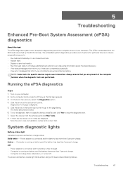
... are displayed. On the boot menu screen, select the Diagnostics option. 4. To run a diagnostic test on your hardware. Computer is displayed. 5. The power and battery-status light blinks amber along with the BIOS and is launched by the BIOS internally. Turn on a specific device, press Esc and click Yes to stop the diagnostic test. 7. Diagnostics front page is running on battery and the battery has less than 5 percent charge. Click...
... are displayed. On the boot menu screen, select the Diagnostics option. 4. To run a diagnostic test on your hardware. Computer is displayed. 5. The power and battery-status light blinks amber along with the BIOS and is launched by the BIOS internally. Turn on a specific device, press Esc and click Yes to stop the diagnostic test. 7. Diagnostics front page is running on battery and the battery has less than 5 percent charge. Click...
Service Manual
Page 68
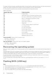
... ROM (Read-Only Memory) failure No memory or RAM (Random-Access Memory) detected Memory or RAM (Random-Access Memory) failure Invalid memory installed System-board or chipset error Display failure LCD power rail failure. Camera is detected. Dell SupportAssist OS Recovery is a standalone tool that needs the BIOS update. 68 Troubleshooting For more information see Dell SupportAssist OS Recovery User's Guide at www.dell.com/support. 3. Flashing BIOS (USB key) Steps 1. Copy the BIOS setup program file to the computer that is unable to boot to the operating...
... ROM (Read-Only Memory) failure No memory or RAM (Random-Access Memory) detected Memory or RAM (Random-Access Memory) failure Invalid memory installed System-board or chipset error Display failure LCD power rail failure. Camera is detected. Dell SupportAssist OS Recovery is a standalone tool that needs the BIOS update. 68 Troubleshooting For more information see Dell SupportAssist OS Recovery User's Guide at www.dell.com/support. 3. Flashing BIOS (USB key) Steps 1. Copy the BIOS setup program file to the computer that is unable to boot to the operating...
Service Manual
Page 69
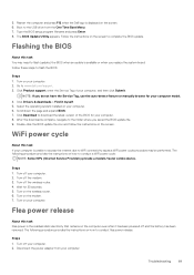
....dell.com/support. 3. Turn off the modem. 3. Turn off your computer. 6. Turn off the wireless router. 4. Type the BIOS setup program filename and press Enter. 8. Go to WiFi connectivity issues a WiFi power cycle procedure may need to download the latest version of your computer. 8. Click Product support, enter the Service Tag of the BIOS for your computer, and then click Submit. Disconnect the power adapter from the One Time Boot Menu. 7. Select the operating system installed...
....dell.com/support. 3. Turn off the modem. 3. Turn off your computer. 6. Turn off the wireless router. 4. Type the BIOS setup program filename and press Enter. 8. Go to WiFi connectivity issues a WiFi power cycle procedure may need to download the latest version of your computer. 8. Click Product support, enter the Service Tag of the BIOS for your computer, and then click Submit. Disconnect the power adapter from the One Time Boot Menu. 7. Select the operating system installed...


