Service Manual
Page 1
... any manner whatsoever without notice. © 2009 Dell Inc. Dell™ Inspiron™ 535s/537s/545s/546s Service Manual Technical Overview Before You Begin Computer Cover Support Bracket Front Bezel Memory PCI and PCI Express Cards Drives Models DCSLE and DCSLF Fans Front I/O Panel Processor System Board Power Supply Battery System Setup Notes, Cautions, and Warnings...
... any manner whatsoever without notice. © 2009 Dell Inc. Dell™ Inspiron™ 535s/537s/545s/546s Service Manual Technical Overview Before You Begin Computer Cover Support Bracket Front Bezel Memory PCI and PCI Express Cards Drives Models DCSLE and DCSLF Fans Front I/O Panel Processor System Board Power Supply Battery System Setup Notes, Cautions, and Warnings...
Service Manual
Page 33
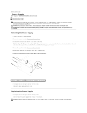
... from the system board and drives. Remove all screws may cause electrical shock as you replace them to Contents Page Power Supply Dell™ Inspiron™ 535s/537s/545s/546s Service Manual Removing the Power Supply Replacing the Power Supply WARNING: Before working inside your computer, read the safety information that shipped with any cover(s) (including computer covers, bezels...
... from the system board and drives. Remove all screws may cause electrical shock as you replace them to Contents Page Power Supply Dell™ Inspiron™ 535s/537s/545s/546s Service Manual Removing the Power Supply Replacing the Power Supply WARNING: Before working inside your computer, read the safety information that shipped with any cover(s) (including computer covers, bezels...
Service Manual
Page 34
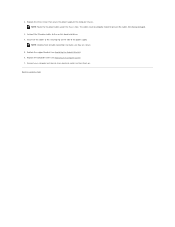
2. Connect the DC power cables to the securing clip on . Replace the computer cover (see Replacing the Support Bracket). 6. Secure all cable connections to prevent the cables from being ...-check all the cables to the system board and drives. 4. Back to the computer chassis. NOTE: Route the DC power cables under the chassis tabs. Replace the three screws that secure the power supply to Contents Page Connect your computer and devices to an electrical outlet, and turn them on the side of...
2. Connect the DC power cables to the securing clip on . Replace the computer cover (see Replacing the Support Bracket). 6. Secure all cable connections to prevent the cables from being ...-check all the cables to the system board and drives. 4. Back to the computer chassis. NOTE: Route the DC power cables under the chassis tabs. Replace the three screws that secure the power supply to Contents Page Connect your computer and devices to an electrical outlet, and turn them on the side of...
Service Manual
Page 47
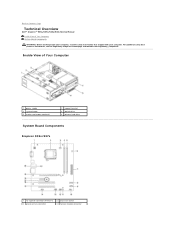
... Components WARNING: Before working inside your computer, read the safety information that shipped with your computer. Back to Contents Page Technical Overview Dell™ Inspiron™ 535s/537s/545s/546s Service Manual Inside View of Your Computer 1 power supply 3 system board 5 media card reader (optional) 2 support bracket 4 optical drive 6 primary hard drive System Board Components...
... Components WARNING: Before working inside your computer, read the safety information that shipped with your computer. Back to Contents Page Technical Overview Dell™ Inspiron™ 535s/537s/545s/546s Service Manual Inside View of Your Computer 1 power supply 3 system board 5 media card reader (optional) 2 support bracket 4 optical drive 6 primary hard drive System Board Components...
SETUP GUIDE
Page 20
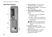
Using Your Inspiron™ Desktop Back View Features 5 4 3 1 2 18 1 Power connector - Appearance may not be available on some models. 4 Expansion card slots - Power is available for the power supply or the power supply is not available for the power supply. • No light - For power cable connection. For selecting the voltage rating. 3 Power supply diagnostic light - Power is not working. Indicates power availability for any...
Using Your Inspiron™ Desktop Back View Features 5 4 3 1 2 18 1 Power connector - Appearance may not be available on some models. 4 Expansion card slots - Power is available for the power supply or the power supply is not available for the power supply. • No light - For power cable connection. For selecting the voltage rating. 3 Power supply diagnostic light - Power is not working. Indicates power availability for any...

SETUP GUIDE
Page 27
... the power supply diagnostic light on the back of the system is on. If the power light is solid white and the computer is in sleep state. If the power light is blinking amber - If the power light is solid amber - Also bypass power protection devices, power strips, and power extension cables...Press a key on the keyboard, move the pointer on the Dell Support website at support.dell.com). 25 Ensure that the power strip is turned on. The computer is receiving electrical power, but a device might be connected or powered on. The computer is either turned off - The display may...
... the power supply diagnostic light on the back of the system is on. If the power light is solid white and the computer is in sleep state. If the power light is blinking amber - If the power light is solid amber - Also bypass power protection devices, power strips, and power extension cables...Press a key on the keyboard, move the pointer on the Dell Support website at support.dell.com). 25 Ensure that the power strip is turned on. The computer is receiving electrical power, but a device might be connected or powered on. The computer is either turned off - The display may...

SETUP GUIDE
Page 56
... 35,000 ft) Airborne G2 or lower as defined by contaminant ISA-S71.04-1985 level Power DC Power Supply Wattage 250 W 54 Power Maximum heat dissipation 852.5 BTU/hr NOTE: Heat dissipation is calculated by using the power supply wattage rating Voltage 115/230 VAC, 50/60 Hz, 6/3 A Coin-cell battery 3-V CR2032 lithium coin cell...
... 35,000 ft) Airborne G2 or lower as defined by contaminant ISA-S71.04-1985 level Power DC Power Supply Wattage 250 W 54 Power Maximum heat dissipation 852.5 BTU/hr NOTE: Heat dissipation is calculated by using the power supply wattage rating Voltage 115/230 VAC, 50/60 Hz, 6/3 A Coin-cell battery 3-V CR2032 lithium coin cell...


