
Service Manual
Page 44
... drive (see Removing the Processor). 8. Note the routing of all cables from each memory socket so that the memory modules...processor fan and heat sink assembly (see the Regulatory Compliance Homepage at www.dell.com/regulatory_compliance. Back to Contents Page System Board Dell™ Inspiron™ 535s/537s...Processor Fan and Heat Sink Assembly). 7. Remove any cover(s) (including computer covers, bezels, filler brackets, front-panel inserts, etc.) removed. Removing the System Board 1. Remove the computer cover (see Removing the Support Bracket). 4. Remove the support...
... drive (see Removing the Processor). 8. Note the routing of all cables from each memory socket so that the memory modules...processor fan and heat sink assembly (see the Regulatory Compliance Homepage at www.dell.com/regulatory_compliance. Back to Contents Page System Board Dell™ Inspiron™ 535s/537s...Processor Fan and Heat Sink Assembly). 7. Remove any cover(s) (including computer covers, bezels, filler brackets, front-panel inserts, etc.) removed. Removing the System Board 1. Remove the computer cover (see Removing the Support Bracket). 4. Remove the support...

Service Manual
Page 46
...Computer Cover). 11. 2. Replace the screws that secure the system board to Contents Page Replace the memory modules into the memory sockets at the same locations from the system board. Replace the computer cover (see Replacing an Optical Drive). 8. Connect your computer... Connect the cables that the processor fan and heat sink assembly is correctly seated and secure. 4. Back to the chassis. 3. Replace any add-in cards on . Replace the processor (see Replacing the Support Bracket). 10. Replace the support bracket (see Replacing the Processor). 5. CAUTION: Ensure that you...
...Computer Cover). 11. 2. Replace the screws that secure the system board to Contents Page Replace the memory modules into the memory sockets at the same locations from the system board. Replace the computer cover (see Replacing an Optical Drive). 8. Connect your computer... Connect the cables that the processor fan and heat sink assembly is correctly seated and secure. 4. Back to the chassis. 3. Replace any add-in cards on . Replace the processor (see Replacing the Support Bracket). 10. Replace the support bracket (see Replacing the Processor). 5. CAUTION: Ensure that you...
Service Manual
Page 47
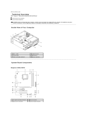
Back to Contents Page Technical Overview Dell™ Inspiron™ 535s/537s/545s/546s Service Manual Inside View of Your Computer 1 power supply 3 system board 5 media card reader (optional) 2 support bracket 4 optical drive 6 primary hard drive System Board Components Inspiron 535s/537s 1 12 V power connector (ATX12V1) 3 processor fan connector 2 processor socket 4 memory module connector For additional safety best practices information...
Back to Contents Page Technical Overview Dell™ Inspiron™ 535s/537s/545s/546s Service Manual Inside View of Your Computer 1 power supply 3 system board 5 media card reader (optional) 2 support bracket 4 optical drive 6 primary hard drive System Board Components Inspiron 535s/537s 1 12 V power connector (ATX12V1) 3 processor fan connector 2 processor socket 4 memory module connector For additional safety best practices information...


