
Service Manual
Page 3
Contents 1 Before You Begin 9 Recommended Tools 9 Turning Off Your Computer 9 Before Working Inside Your Computer 10 2 Top Cover 13 Removing the Top Cover 13 Replacing the Top Cover 14 3 Battery 15 Removing the Battery 15 Replacing the Battery 16 4 Module Cover 17 Removing the Module Cover 17 Replacing the Module Cover 18 5 Memory Module(s 19 Removing the Memory Module(s 19 Contents 3
Contents 1 Before You Begin 9 Recommended Tools 9 Turning Off Your Computer 9 Before Working Inside Your Computer 10 2 Top Cover 13 Removing the Top Cover 13 Replacing the Top Cover 14 3 Battery 15 Removing the Battery 15 Replacing the Battery 16 4 Module Cover 17 Removing the Module Cover 17 Replacing the Module Cover 18 5 Memory Module(s 19 Removing the Memory Module(s 19 Contents 3

Service Manual
Page 5
... Hinge Cover 53 Replacing the Hinge Cover 55 12 Camera Module 57 Removing the Camera Module 57 Replacing the Camera Module 58 13 Coin-Cell Battery 61 Removing the Coin-Cell Battery 61 Replacing the Coin-Cell...
... Hinge Cover 53 Replacing the Hinge Cover 55 12 Camera Module 57 Removing the Camera Module 57 Replacing the Camera Module 58 13 Coin-Cell Battery 61 Removing the Coin-Cell Battery 61 Replacing the Coin-Cell...

Service Manual
Page 11
CAUTION: To help prevent damage to the system board, remove the main battery (see "Removing the Battery" on page 15) before working inside the computer. 7 Remove the battery (see "Removing the Battery" on page 15). 8 Turn the computer top-side up, open the display, and press the power button to ground the system board. Before You Begin 11
CAUTION: To help prevent damage to the system board, remove the main battery (see "Removing the Battery" on page 15) before working inside the computer. 7 Remove the battery (see "Removing the Battery" on page 15). 8 Turn the computer top-side up, open the display, and press the power button to ground the system board. Before You Begin 11

Service Manual
Page 13
... electrostatic discharge, ground yourself by using a wrist grounding strap or by your computer. Damage due to servicing that is not authorized by Dell is not covered by periodically touching an unpainted metal surface (such as a connector on your computer). Removing the Top Cover 1 Follow the... page 9. 2 Press and hold the release button that secures the top cover to the system board, remove the main battery (see the Regulatory Compliance Homepage at dell.com/regulatory_compliance. CAUTION: To help prevent damage to the display back cover. 3 Slide and lift the top cover. Top ...
... electrostatic discharge, ground yourself by using a wrist grounding strap or by your computer. Damage due to servicing that is not authorized by Dell is not covered by periodically touching an unpainted metal surface (such as a connector on your computer). Removing the Top Cover 1 Follow the... page 9. 2 Press and hold the release button that secures the top cover to the system board, remove the main battery (see the Regulatory Compliance Homepage at dell.com/regulatory_compliance. CAUTION: To help prevent damage to the display back cover. 3 Slide and lift the top cover. Top ...

Service Manual
Page 15
...the computer and turn it over. 3 Slide the battery release latch and the battery lock latch to the unlock positions. 4 Slide and lift the battery out of the battery bay. Damage due to the computer, use batteries designed for this particular Dell computer. CAUTION: To avoid electrostatic discharge, ground ... by using a wrist grounding strap or by your warranty. Battery 15 Do not use only the battery designed for other Dell computers. CAUTION: To avoid damage to servicing that shipped with your computer. Removing the Battery 1 Follow the instructions in "Before You Begin" on your...
...the computer and turn it over. 3 Slide the battery release latch and the battery lock latch to the unlock positions. 4 Slide and lift the battery out of the battery bay. Damage due to the computer, use batteries designed for this particular Dell computer. CAUTION: To avoid electrostatic discharge, ground ... by using a wrist grounding strap or by your warranty. Battery 15 Do not use only the battery designed for other Dell computers. CAUTION: To avoid damage to servicing that shipped with your computer. Removing the Battery 1 Follow the instructions in "Before You Begin" on your...

Service Manual
Page 16
3 2 1 1 battery release latch 3 battery lock latch 2 battery Replacing the Battery 1 Follow the instructions in "Before You Begin" on page 9. 2 Slide the battery into the battery bay until it clicks into place. 3 Slide the battery lock latch to the lock position. 16 Battery
3 2 1 1 battery release latch 3 battery lock latch 2 battery Replacing the Battery 1 Follow the instructions in "Before You Begin" on page 9. 2 Slide the battery into the battery bay until it clicks into place. 3 Slide the battery lock latch to the lock position. 16 Battery

Service Manual
Page 17
...4 Using your fingertips, release the tabs on the module cover from the slots on page 9. 2 Remove the battery (see the Regulatory Compliance Homepage at dell.com/regulatory_compliance. Module Cover 17 4 Module Cover WARNING: Before working inside your computer, read the safety information that ...: To help prevent damage to servicing that shipped with your warranty. Damage due to the system board, remove the main battery (see "Removing the Battery" on page 15) before working inside the computer. CAUTION: Only a certified service technician should perform repairs on your computer...
...4 Using your fingertips, release the tabs on the module cover from the slots on page 9. 2 Remove the battery (see the Regulatory Compliance Homepage at dell.com/regulatory_compliance. Module Cover 17 4 Module Cover WARNING: Before working inside your computer, read the safety information that ...: To help prevent damage to servicing that shipped with your warranty. Damage due to the system board, remove the main battery (see "Removing the Battery" on page 15) before working inside the computer. CAUTION: Only a certified service technician should perform repairs on your computer...

Service Manual
Page 18
3 2 1 1 tabs 3 captive screw 2 module cover Replacing the Module Cover CAUTION: To avoid damage to the computer, use only the battery designed for this particular Dell computer. 1 Follow the instructions in "Before You Begin" on page 9. 2 Align the tabs on the module cover with the slots on the computer base and snap the module cover into place. 3 Tighten the captive screw that secures the module cover to the computer base. 4 Replace the battery (see "Replacing the Battery" on page 16). 18 Module Cover
3 2 1 1 tabs 3 captive screw 2 module cover Replacing the Module Cover CAUTION: To avoid damage to the computer, use only the battery designed for this particular Dell computer. 1 Follow the instructions in "Before You Begin" on page 9. 2 Align the tabs on the module cover with the slots on the computer base and snap the module cover into place. 3 Tighten the captive screw that secures the module cover to the computer base. 4 Replace the battery (see "Replacing the Battery" on page 16). 18 Module Cover

Service Manual
Page 19
... tools to spread the memory module securing clips. 4 Use your fingertips to the system board, remove the main battery (see the Regulatory Compliance Homepage at dell.com/regulatory_compliance. Your computer has two user-accessible SODIMM sockets, labeled DIMM A and DIMM B, that is not ... inside your computer, read the safety information that shipped with your computer. For additional safety best practices information, see "Removing the Battery" on your computer warranty. CAUTION: To help prevent damage to carefully spread apart the securing clips on page 17). NOTE: Memory...
... tools to spread the memory module securing clips. 4 Use your fingertips to the system board, remove the main battery (see the Regulatory Compliance Homepage at dell.com/regulatory_compliance. Your computer has two user-accessible SODIMM sockets, labeled DIMM A and DIMM B, that is not ... inside your computer, read the safety information that shipped with your computer. For additional safety best practices information, see "Removing the Battery" on your computer warranty. CAUTION: To help prevent damage to carefully spread apart the securing clips on page 17). NOTE: Memory...

Service Manual
Page 21
...;System and SecuritySystem. 2 1 1 tab 2 notch 4 Replace the module cover (see "Replacing the Module Cover" on page 18). 5 Replace the battery (see "Replacing the Battery" on page 16), or connect the AC adapter to the computer. 6 Turn on the computer, replace all screws and ensure that no stray screws...
...;System and SecuritySystem. 2 1 1 tab 2 notch 4 Replace the module cover (see "Replacing the Module Cover" on page 18). 5 Replace the battery (see "Replacing the Battery" on page 16), or connect the AC adapter to the computer. 6 Turn on the computer, replace all screws and ensure that no stray screws...

Service Manual
Page 23
...Drive 1 Follow the instructions in "Before You Begin" on page 9. 2 Remove the battery (see "Removing the Battery" on page 15). 3 Remove the module cover (see the Regulatory Compliance Homepage at dell.com/regulatory_compliance. drive assembly out. 5 Slide the optical-drive assembly out of the ... Cover" on page 17). 4 Using a plastic scribe, push the optical drive bracket to the system board, remove the main battery (see "Removing the Battery" on your warranty. Optical Drive 23 CAUTION: Only a certified service technician should perform repairs on page 15) before working inside...
...Drive 1 Follow the instructions in "Before You Begin" on page 9. 2 Remove the battery (see "Removing the Battery" on page 15). 3 Remove the module cover (see the Regulatory Compliance Homepage at dell.com/regulatory_compliance. drive assembly out. 5 Slide the optical-drive assembly out of the ... Cover" on page 17). 4 Using a plastic scribe, push the optical drive bracket to the system board, remove the main battery (see "Removing the Battery" on your warranty. Optical Drive 23 CAUTION: Only a certified service technician should perform repairs on page 15) before working inside...

Service Manual
Page 24
Failure to do so may result in "Before You Begin" on page 9. 2 Slide the optical-drive assembly into the optical-drive bay until it is fully seated. 3 Replace the module cover (see "Replacing the Module Cover" on page 18). 4 Replace the battery (see "Replacing the Battery" on the computer, replace all screws and ensure that no stray screws remain inside the computer. CAUTION: Before turning on page 16). 2 1 1 optical-drive assembly 2 plastic scribe Replacing the Optical Drive 1 Follow the instructions in damage to the computer. 24 Optical Drive
Failure to do so may result in "Before You Begin" on page 9. 2 Slide the optical-drive assembly into the optical-drive bay until it is fully seated. 3 Replace the module cover (see "Replacing the Module Cover" on page 18). 4 Replace the battery (see "Replacing the Battery" on the computer, replace all screws and ensure that no stray screws remain inside the computer. CAUTION: Before turning on page 16). 2 1 1 optical-drive assembly 2 plastic scribe Replacing the Optical Drive 1 Follow the instructions in damage to the computer. 24 Optical Drive

Service Manual
Page 27
... release the tabs on the plam rest. 5 Lift and slide the keyboard to the system board, remove the main battery (see "Removing the Battery" on page 15) before working inside the computer. CAUTION: To avoid electrostatic discharge, ground yourself by using a wrist... 27 For additional safety best practices information, see "Removing the Battery" on the palm rest. CAUTION: Only a certified service technician should perform repairs on page 9. 2 Remove the battery (see the Regulatory Compliance Homepage at dell.com/regulatory_compliance. Removing the Keyboard 1 Follow the instructions in "...
... release the tabs on the plam rest. 5 Lift and slide the keyboard to the system board, remove the main battery (see "Removing the Battery" on page 15) before working inside the computer. CAUTION: To avoid electrostatic discharge, ground yourself by using a wrist... 27 For additional safety best practices information, see "Removing the Battery" on the palm rest. CAUTION: Only a certified service technician should perform repairs on page 9. 2 Remove the battery (see the Regulatory Compliance Homepage at dell.com/regulatory_compliance. Removing the Keyboard 1 Follow the instructions in "...

Service Manual
Page 30
6 Replace the battery (see "Replacing the Battery" on page 16). 30 Keyboard
6 Replace the battery (see "Replacing the Battery" on page 16). 30 Keyboard

Service Manual
Page 31
...damage to servicing that secure the palm-rest assembly to the computer base. For additional safety best practices information, see "Removing the Battery" on your warranty. CAUTION: Only a certified service technician should perform repairs on page 15). 3 Remove the six screws that is not authorized... by Dell is not covered by periodically touching an unpainted metal surface (such as a connector on page 15) before working inside the computer. Palm...
...damage to servicing that secure the palm-rest assembly to the computer base. For additional safety best practices information, see "Removing the Battery" on your warranty. CAUTION: Only a certified service technician should perform repairs on page 15). 3 Remove the six screws that is not authorized... by Dell is not covered by periodically touching an unpainted metal surface (such as a connector on page 15) before working inside the computer. Palm...

Service Manual
Page 35
CAUTION: Before turning on page 16). Failure to do so may result in damage to the computer base. 8 Replace the battery (see "Replacing the Battery" on the computer, replace all screws and ensure that secure the palm-rest assembly to the computer. Palm-Rest Assembly 35 6 Close the display and turn the computer over. 7 Replace the six screws that no stray screws remain inside the computer.
CAUTION: Before turning on page 16). Failure to do so may result in damage to the computer base. 8 Replace the battery (see "Replacing the Battery" on the computer, replace all screws and ensure that secure the palm-rest assembly to the computer. Palm-Rest Assembly 35 6 Close the display and turn the computer over. 7 Replace the six screws that no stray screws remain inside the computer.

Service Manual
Page 37
...the system board, remove the main battery (see "Removing the Battery" on page 15) before working inside the computer. If you are removing the WiMax/WWAN Mini-Card: a Remove the module cover (see the Regulatory Compliance Homepage at www.dell.com/regulatory_compliance. Your computer has ...Mini-Card slot for Worldwide Interoperability for Mini-Cards from sources other than Dell. Removing the Mini-Card(s) 1 Follow the instructions in "Before You Begin" on page 9. 2 Remove the battery (see "Removing the Battery" on page 17). CAUTION: Only a certified service technician should perform repairs...
...the system board, remove the main battery (see "Removing the Battery" on page 15) before working inside the computer. If you are removing the WiMax/WWAN Mini-Card: a Remove the module cover (see the Regulatory Compliance Homepage at www.dell.com/regulatory_compliance. Your computer has ...Mini-Card slot for Worldwide Interoperability for Mini-Cards from sources other than Dell. Removing the Mini-Card(s) 1 Follow the instructions in "Before You Begin" on page 9. 2 Remove the battery (see "Removing the Battery" on page 17). CAUTION: Only a certified service technician should perform repairs...
Service Manual
Page 40
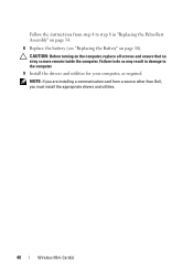
CAUTION: Before turning on page 16). Follow the instructions from a source other than Dell, you are installing a communication card from step 4 to step 8 in damage to do so may result in "Replacing the Palm-Rest Assembly" on page 34. 8 Replace the battery (see "Replacing the Battery" on the computer, replace all screws and ensure that no stray screws remain inside the computer. Failure to the computer. 9 Install the drivers and utilities for your computer, as required. NOTE: If you must install the appropriate drivers and utilities. 40 Wireless Mini-Card(s)
CAUTION: Before turning on page 16). Follow the instructions from a source other than Dell, you are installing a communication card from step 4 to step 8 in damage to do so may result in "Replacing the Palm-Rest Assembly" on page 34. 8 Replace the battery (see "Replacing the Battery" on the computer, replace all screws and ensure that no stray screws remain inside the computer. Failure to the computer. 9 Install the drivers and utilities for your computer, as required. NOTE: If you must install the appropriate drivers and utilities. 40 Wireless Mini-Card(s)

Service Manual
Page 41
... CAUTION: To avoid electrostatic discharge, ground yourself by using a wrist grounding strap or by your computer). For additional safety best practices information, see "Removing the Battery" on your warranty. Damage due to the system board, remove the main battery (see the Regulatory Compliance Homepage at dell.com/regulatory_compliance.
... CAUTION: To avoid electrostatic discharge, ground yourself by using a wrist grounding strap or by your computer). For additional safety best practices information, see "Removing the Battery" on your warranty. Damage due to the system board, remove the main battery (see the Regulatory Compliance Homepage at dell.com/regulatory_compliance.

Service Manual
Page 44
... Begin" on page 9. 2 Remove the top cover (see "Removing the Top Cover" on page 13). 3 Remove the display assembly (see "Replacing the Battery" on page 16). CAUTION: Before turning on page 41). Be careful when removing it to prevent damaging the display bezel. 4 Using your fingertips, carefully pry... up the inside the computer. Display Bezel Removing the Display Bezel 1 Follow the instructions in damage to the computer base. 8 Replace the battery (see "Removing the Display Assembly" on the computer, replace all screws and ensure that secure the display assembly to the computer.
... Begin" on page 9. 2 Remove the top cover (see "Removing the Top Cover" on page 13). 3 Remove the display assembly (see "Replacing the Battery" on page 16). CAUTION: Before turning on page 41). Be careful when removing it to prevent damaging the display bezel. 4 Using your fingertips, carefully pry... up the inside the computer. Display Bezel Removing the Display Bezel 1 Follow the instructions in damage to the computer base. 8 Replace the battery (see "Removing the Display Assembly" on the computer, replace all screws and ensure that secure the display assembly to the computer.


