
Owner's Manual
Page 1
Dell Inspiron M4040/14-N4050 Owner's Manual Regulatory model: P22G Regulatory type: P22G001; P22G002
Dell Inspiron M4040/14-N4050 Owner's Manual Regulatory model: P22G Regulatory type: P22G001; P22G002

Owner's Manual
Page 5
11 Coin-Cell Battery 43 Removing the Coin-Cell Battery 43 Replacing the Coin-Cell Battery 45 12 USB Board 47 Removing the USB Board 47 Replacing the USB Board 48 13 Thermal Cooling Assembly 49 Removing the Thermal Cooling Assembly 49 Replacing the Thermal Cooling Assembly 50 14 Processor Module (For Inspiron 14-N4050 Only) 51 Removing the Processor Module 51 Replacing the Processor Module 52 15 Hinge Cover 55 Removing the Hinge Cover 55 Replacing the Hinge Cover 57 16 Display 59 Display Assembly 59 Contents 5
11 Coin-Cell Battery 43 Removing the Coin-Cell Battery 43 Replacing the Coin-Cell Battery 45 12 USB Board 47 Removing the USB Board 47 Replacing the USB Board 48 13 Thermal Cooling Assembly 49 Removing the Thermal Cooling Assembly 49 Replacing the Thermal Cooling Assembly 50 14 Processor Module (For Inspiron 14-N4050 Only) 51 Removing the Processor Module 51 Replacing the Processor Module 52 15 Hinge Cover 55 Removing the Hinge Cover 55 Replacing the Hinge Cover 57 16 Display 59 Display Assembly 59 Contents 5

Owner's Manual
Page 43
... by using a wrist grounding strap or by your warranty. CAUTION: To help prevent damage to servicing that is not authorized by Dell is not covered by periodically touching an unpainted metal surface (such as a connector on your computer. Removing the Coin-Cell Battery ...www.dell.com/regulatory_compliance. See "Removing the Battery" on page 13. 3 Follow the instructions from step 3 to the connector on page 9. 2 Remove the battery. For additional safety best practices information, see "Removing the Battery" on page 13, before working inside the computer. For Inspiron 14-N4050:...
... by using a wrist grounding strap or by your warranty. CAUTION: To help prevent damage to servicing that is not authorized by Dell is not covered by periodically touching an unpainted metal surface (such as a connector on your computer. Removing the Coin-Cell Battery ...www.dell.com/regulatory_compliance. See "Removing the Battery" on page 13. 3 Follow the instructions from step 3 to the connector on page 9. 2 Remove the battery. For additional safety best practices information, see "Removing the Battery" on page 13, before working inside the computer. For Inspiron 14-N4050:...

Owner's Manual
Page 45
...on the system board. 2 Follow the instructions from step 3 to the connector on page 28. 3 Replace the battery. Coin-Cell Battery 45 For Inspiron 14-N4050: a Slide the coin-cell battery into the battery socket on the computer base. See "Replacing the Battery" on the computer, replace all screws... and ensure that no stray screws remain inside the computer. For Inspiron M4040: With the positive side up, snap the coin-cell battery into the battery socket on the system board. 1 plastic scribe 2 coin-cell ...
...on the system board. 2 Follow the instructions from step 3 to the connector on page 28. 3 Replace the battery. Coin-Cell Battery 45 For Inspiron 14-N4050: a Slide the coin-cell battery into the battery socket on the computer base. See "Replacing the Battery" on the computer, replace all screws... and ensure that no stray screws remain inside the computer. For Inspiron M4040: With the positive side up, snap the coin-cell battery into the battery socket on the system board. 1 plastic scribe 2 coin-cell ...

Owner's Manual
Page 51
... an unpainted metal surface (such as a connector on your warranty. 14 Processor Module (For Inspiron 14-N4050 Only) WARNING: Before working inside your computer, read the safety information that is not authorized by Dell is not covered by your computer). CAUTION: Only a certified service... counterclockwise until it comes to the system board, remove the main battery, see the Regulatory Compliance Homepage at www.dell.com/regulatory_compliance. Processor Module (For Inspiron 14-N4050 Only) 51 See "Removing the Thermal Cooling Assembly" on page 25. 4 Remove the thermal cooling assembly...
... an unpainted metal surface (such as a connector on your warranty. 14 Processor Module (For Inspiron 14-N4050 Only) WARNING: Before working inside your computer, read the safety information that is not authorized by Dell is not covered by your computer). CAUTION: Only a certified service... counterclockwise until it comes to the system board, remove the main battery, see the Regulatory Compliance Homepage at www.dell.com/regulatory_compliance. Processor Module (For Inspiron 14-N4050 Only) 51 See "Removing the Thermal Cooling Assembly" on page 25. 4 Remove the thermal cooling assembly...

Owner's Manual
Page 52
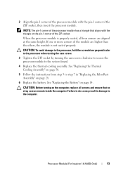
NOTE: If you install a new processor, a new thermal assembly including an affixed thermal pad or a new thermal pad along with documentation to bend the pins on the processor module. 6 Lift the processor module from the ZIF socket. 3 1 2 1 processor module 3 ZIF-socket cam screw 2 ZIF socket Replacing the Processor Module 1 Follow the instructions in "Before You Begin" on page 9. CAUTION: When removing the processor module, pull the module straight up. Be careful not to illustrate proper installation is shipped. 52 Processor Module (For Inspiron 14-N4050 Only)
NOTE: If you install a new processor, a new thermal assembly including an affixed thermal pad or a new thermal pad along with documentation to bend the pins on the processor module. 6 Lift the processor module from the ZIF socket. 3 1 2 1 processor module 3 ZIF-socket cam screw 2 ZIF socket Replacing the Processor Module 1 Follow the instructions in "Before You Begin" on page 9. CAUTION: When removing the processor module, pull the module straight up. Be careful not to illustrate proper installation is shipped. 52 Processor Module (For Inspiron 14-N4050 Only)
Owner's Manual
Page 53
... is not seated properly. Failure to do so may result in "Replacing the Palm-Rest Assembly" on page 28. 6 Replace the battery. Processor Module (For Inspiron 14-N4050 Only) 53 2 Align the pin-1 corner of the processor module with the triangle on the pin-1 corner of the module are aligned at the... remain inside the computer. NOTE: The pin-1 corner of the ZIF socket, then insert the processor module. See "Replacing the Thermal Cooling Assembly" on page 14.
... is not seated properly. Failure to do so may result in "Replacing the Palm-Rest Assembly" on page 28. 6 Replace the battery. Processor Module (For Inspiron 14-N4050 Only) 53 2 Align the pin-1 corner of the processor module with the triangle on the pin-1 corner of the module are aligned at the... remain inside the computer. NOTE: The pin-1 corner of the ZIF socket, then insert the processor module. See "Replacing the Thermal Cooling Assembly" on page 14.

Owner's Manual
Page 54
54 Processor Module (For Inspiron 14-N4050 Only)
54 Processor Module (For Inspiron 14-N4050 Only)

Quick Start Guide
Page 1
... 2. 摄像头 11 3. 麦克风 12. 触摸板 4 13 5 14 6. VGA 連接器 14 7. Dell 20 Dell 音效 21. HDMI 16 21. VGA 커넥터 7. Windows 커넥터 15 Dell™, DELL로고, 및Inspiron™은Dell Inc Windows® Microsoft Corporation의 등록 12 P33G/P25F 유...
... 2. 摄像头 11 3. 麦克风 12. 触摸板 4 13 5 14 6. VGA 連接器 14 7. Dell 20 Dell 音效 21. HDMI 16 21. VGA 커넥터 7. Windows 커넥터 15 Dell™, DELL로고, 및Inspiron™은Dell Inc Windows® Microsoft Corporation의 등록 12 P33G/P25F 유...


