

Owner's Manual
Page 1
Dell Inspiron 11 Owner's Manual Computer model: Inspiron 3137 Regulatory model: P19T Regulatory type: P19T001
Dell Inspiron 11 Owner's Manual Computer model: Inspiron 3137 Regulatory model: P19T Regulatory type: P19T001
Owner's Manual
Page 3
Contents Before Working Inside Your Computer 7 Before You Begin 7 Recommended Tools 7 Safety Instructions 8 After Working Inside Your Computer 9 Removing the Base Cover 10 Procedure 10 Replacing the Base Cover 11 Procedure 11 Removing the Battery 12 Prerequisites 12 Procedure 12 Replacing the Battery 13 Procedure 13 Postrequisites 13 Removing the Memory Module(s 14 Prerequisites 14 Procedure 14 Replacing the Memory Module(s 16 Procedure 16 Postrequisites 16 Removing the Hard Drive 17 Prerequisites 17 Procedure 18 Contents | 3
Contents Before Working Inside Your Computer 7 Before You Begin 7 Recommended Tools 7 Safety Instructions 8 After Working Inside Your Computer 9 Removing the Base Cover 10 Procedure 10 Replacing the Base Cover 11 Procedure 11 Removing the Battery 12 Prerequisites 12 Procedure 12 Replacing the Battery 13 Procedure 13 Postrequisites 13 Removing the Memory Module(s 14 Prerequisites 14 Procedure 14 Replacing the Memory Module(s 16 Procedure 16 Postrequisites 16 Removing the Hard Drive 17 Prerequisites 17 Procedure 18 Contents | 3
Owner's Manual
Page 5
... 31 Prerequisites 31 Procedure 31 Replacing the Heat Sink 32 Procedure 32 Postrequisites 32 Removing the Power-Adapter Port 33 Prerequisites 33 Procedure 33 Replacing the Power-Adapter Port 34 Procedure 34 Postrequisites 34 Removing the System Board 35 Prerequisites 35 Procedure 36 Replacing the System Board 39 Procedure 39 Postrequisites 39 Entering the Service Tag in the BIOS 39 Removing the Display Assembly 40 Prerequisites 40 Procedure...
... 31 Prerequisites 31 Procedure 31 Replacing the Heat Sink 32 Procedure 32 Postrequisites 32 Removing the Power-Adapter Port 33 Prerequisites 33 Procedure 33 Replacing the Power-Adapter Port 34 Procedure 34 Postrequisites 34 Removing the System Board 35 Prerequisites 35 Procedure 36 Replacing the System Board 39 Procedure 39 Postrequisites 39 Entering the Service Tag in the BIOS 39 Removing the Display Assembly 40 Prerequisites 40 Procedure...
Owner's Manual
Page 7
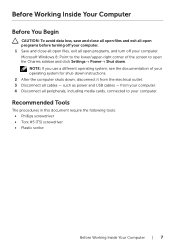
... of your operating system for shut-down instructions. 2 After the computer shuts down . NOTE: If you use a different operating system, see the documentation of the screen to your computer. such as power and USB cables - Before Working Inside Your Computer Before You Begin CAUTION: To avoid data loss, save and close all open files and exit all open programs before turning off...
... of your operating system for shut-down instructions. 2 After the computer shuts down . NOTE: If you use a different operating system, see the documentation of the screen to your computer. such as power and USB cables - Before Working Inside Your Computer Before You Begin CAUTION: To avoid data loss, save and close all open files and exit all open programs before turning off...

Owner's Manual
Page 8
... the computer, make sure that you work surface is authorized to remove the computer cover and access any installed card from the media-card reader. Some cables have connectors with your computer. CAUTION: Before touching anything inside the computer. Safety Instructions Use the following safety guidelines to protect your computer from the network device. 8 | Before Working Inside Your Computer When disconnecting cables, keep them by touching an unpainted metal...
... the computer, make sure that you work surface is authorized to remove the computer cover and access any installed card from the media-card reader. Some cables have connectors with your computer. CAUTION: Before touching anything inside the computer. Safety Instructions Use the following safety guidelines to protect your computer from the network device. 8 | Before Working Inside Your Computer When disconnecting cables, keep them by touching an unpainted metal...
Owner's Manual
Page 12
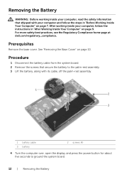
...-rest assembly. 1 2 3 1 battery cable 3 battery 2 screws (4) 4 Turn the computer over, open the display, and press the power button for about five seconds to ground the system board. 12 | Removing the Battery See "Removing the Base Cover" on page 9. For more safety best practices, see the Regulatory Compliance home page at dell.com/regulatory_compliance. After working inside your computer and follow the instructions in "Before Working Inside Your...
...-rest assembly. 1 2 3 1 battery cable 3 battery 2 screws (4) 4 Turn the computer over, open the display, and press the power button for about five seconds to ground the system board. 12 | Removing the Battery See "Removing the Base Cover" on page 9. For more safety best practices, see the Regulatory Compliance home page at dell.com/regulatory_compliance. After working inside your computer and follow the instructions in "Before Working Inside Your...
Owner's Manual
Page 14
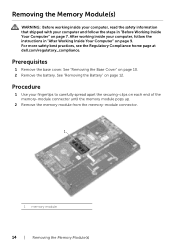
See "Removing the Battery" on page 10. 2 Remove the battery. Prerequisites 1 Remove the base cover. See "Removing the Base Cover" on page 12. After working inside your computer and follow the instructions in "Before Working Inside Your Computer" on page 7. Removing the Memory Module(s) WARNING: Before working inside your computer, read the safety information that shipped with your computer, follow the steps in "After Working Inside Your...
See "Removing the Battery" on page 10. 2 Remove the battery. Prerequisites 1 Remove the base cover. See "Removing the Base Cover" on page 12. After working inside your computer and follow the instructions in "Before Working Inside Your Computer" on page 7. Removing the Memory Module(s) WARNING: Before working inside your computer, read the safety information that shipped with your computer, follow the steps in "After Working Inside Your...
Owner's Manual
Page 15
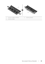
1 3 2 1 memory-module connector 3 memory module 2 securing-clips (2) Removing the Memory Module(s) | 15
1 3 2 1 memory-module connector 3 memory module 2 securing-clips (2) Removing the Memory Module(s) | 15
Owner's Manual
Page 16
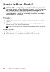
... click, remove the memory module and reinstall it clicks into the connector at dell.com/regulatory_compliance. See "Replacing the Battery" on page 11. 16 | Replacing the Memory Module(s) Postrequisites 1 Replace the battery. For more safety best practices, see the Regulatory Compliance home page at an angle and press the memory module down until it . After working inside your computer and follow the instructions in "Before Working Inside...
... click, remove the memory module and reinstall it clicks into the connector at dell.com/regulatory_compliance. See "Replacing the Battery" on page 11. 16 | Replacing the Memory Module(s) Postrequisites 1 Replace the battery. For more safety best practices, see the Regulatory Compliance home page at an angle and press the memory module down until it . After working inside your computer and follow the instructions in "Before Working Inside...
Owner's Manual
Page 18
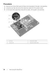
Procedure 1 Remove the screws that secure the hard-drive assembly to the palm-rest assembly. 2 Using the pull-tab, disconnect the hard drive cable from the system board. 3 Lift the hard-drive assembly, along with its cable, off the palm-rest assembly. 1 2 3 4 1 pull-tab 3 screws (2) 2 hard-drive cable 4 hard-drive assembly 18 | Removing the Hard Drive
Procedure 1 Remove the screws that secure the hard-drive assembly to the palm-rest assembly. 2 Using the pull-tab, disconnect the hard drive cable from the system board. 3 Lift the hard-drive assembly, along with its cable, off the palm-rest assembly. 1 2 3 4 1 pull-tab 3 screws (2) 2 hard-drive cable 4 hard-drive assembly 18 | Removing the Hard Drive

Owner's Manual
Page 20
CAUTION: Hard drives are extremely fragile. See "Replacing the Battery" on page 11. 20 | Replacing the Hard Drive CAUTION: To avoid data loss, do not remove the hard drive while the computer is in Sleep or On state. After working inside your computer and follow the instructions in "After Working Inside Your Computer" on page 9. Exercise care when handling the hard drive. For more safety best practices, see...
CAUTION: Hard drives are extremely fragile. See "Replacing the Battery" on page 11. 20 | Replacing the Hard Drive CAUTION: To avoid data loss, do not remove the hard drive while the computer is in Sleep or On state. After working inside your computer and follow the instructions in "After Working Inside Your Computer" on page 9. Exercise care when handling the hard drive. For more safety best practices, see...

Owner's Manual
Page 22
... follow the instructions in "Before Working Inside Your Computer" on page 7. See "Replacing the Battery" on page 11. 22 | Replacing the Wireless Card Connectors on the wireless card Main (white triangle) Auxiliary (black triangle) Antenna-cable color white black Postrequisites 1 Replace the battery. Replacing the Wireless Card WARNING: Before working inside your computer, read the safety information that secures the wireless card to the system board. 2 Connect the antenna cables to the wireless card. For more...
... follow the instructions in "Before Working Inside Your Computer" on page 7. See "Replacing the Battery" on page 11. 22 | Replacing the Wireless Card Connectors on the wireless card Main (white triangle) Auxiliary (black triangle) Antenna-cable color white black Postrequisites 1 Replace the battery. Replacing the Wireless Card WARNING: Before working inside your computer, read the safety information that secures the wireless card to the system board. 2 Connect the antenna cables to the wireless card. For more...
Owner's Manual
Page 25
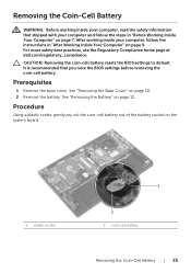
... your computer and follow the instructions in "Before Working Inside Your Computer" on page 10. 2 Remove the battery. See "Removing the Base Cover" on page 7. Removing the Coin-Cell Battery WARNING: Before working inside your computer, read the safety information that you note the BIOS settings before removing the coin-cell battery. CAUTION: Removing the coin-cell battery resets the BIOS settings to default. After working inside your computer, follow...
... your computer and follow the instructions in "Before Working Inside Your Computer" on page 10. 2 Remove the battery. See "Removing the Base Cover" on page 7. Removing the Coin-Cell Battery WARNING: Before working inside your computer, read the safety information that you note the BIOS settings before removing the coin-cell battery. CAUTION: Removing the coin-cell battery resets the BIOS settings to default. After working inside your computer, follow...

Owner's Manual
Page 35
.... 4 Remove the hard-drive. See "Removing the Base Cover" on page 12. 3 Remove the memory module. See "Removing the Battery" on page 10. 2 Remove the battery. See "Removing the Coin-Cell Battery" on page 29. 8 Remove the heat sink. See "Removing the Fan" on page 25. 6 Remove the wireless card. Follow step 2 and step 3 in "Removing the Hard Drive" on page 9. Removing the System Board | 35 After working inside your computer and follow the instructions in "After Working...
.... 4 Remove the hard-drive. See "Removing the Base Cover" on page 12. 3 Remove the memory module. See "Removing the Battery" on page 10. 2 Remove the battery. See "Removing the Coin-Cell Battery" on page 29. 8 Remove the heat sink. See "Removing the Fan" on page 25. 6 Remove the wireless card. Follow step 2 and step 3 in "Removing the Hard Drive" on page 9. Removing the System Board | 35 After working inside your computer and follow the instructions in "After Working...
Owner's Manual
Page 36
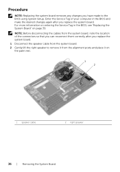
... board. 1 Disconnect the speaker cable from the system board. 2 Gently lift the right speaker to the BIOS using System Setup. For more information on page 39. Enter the Service Tag of your computer in the BIOS, see "Replacing the System Board" on entering the Service Tag in the BIOS and make the desired changes again after you have made to remove it from the system board, note the location...
... board. 1 Disconnect the speaker cable from the system board. 2 Gently lift the right speaker to the BIOS using System Setup. For more information on page 39. Enter the Service Tag of your computer in the BIOS, see "Replacing the System Board" on entering the Service Tag in the BIOS and make the desired changes again after you have made to remove it from the system board, note the location...

Owner's Manual
Page 39
... "Replacing the Memory Module(s)" on page 32. 2 Replace the fan. See "Replacing the Base Cover" on page 22. 4 Replace the hard drive. See "Replacing the Wireless Card" on page 11. Postrequisites 1 Replace the heat sink. See "Replacing the Battery" on page 30. 3 Replace the wireless card. Entering the Service Tag in the BIOS 1 Turn on the computer. 2 At the Dell logo, press to enter System Setup. 3 Navigate to the system board. After working inside your computer and follow the instructions...
... "Replacing the Memory Module(s)" on page 32. 2 Replace the fan. See "Replacing the Base Cover" on page 22. 4 Replace the hard drive. See "Replacing the Wireless Card" on page 11. Postrequisites 1 Replace the heat sink. See "Replacing the Battery" on page 30. 3 Replace the wireless card. Entering the Service Tag in the BIOS 1 Turn on the computer. 2 At the Dell logo, press to enter System Setup. 3 Navigate to the system board. After working inside your computer and follow the instructions...

Owner's Manual
Page 42
See "Replacing the Hard Drive" on page 13. 3 Replace the base cover. See "Replacing the Battery" on page 20. 2 Replace the battery. See "Replacing the Base Cover" on the fan. 6 Connect the antenna cables to the wireless card. Procedure 1 Place the palm-rest assembly on the display assembly. 2 Align the screw holes on the palm-rest assembly with your computer and follow the instructions in "Before Working Inside Your Computer...
See "Replacing the Hard Drive" on page 13. 3 Replace the base cover. See "Replacing the Battery" on page 20. 2 Replace the battery. See "Replacing the Base Cover" on the fan. 6 Connect the antenna cables to the wireless card. Procedure 1 Place the palm-rest assembly on the display assembly. 2 Align the screw holes on the palm-rest assembly with your computer and follow the instructions in "Before Working Inside Your Computer...

Owner's Manual
Page 48
.... 7 Replace the base cover. After working inside your computer and follow the instructions in "Before Working Inside Your Computer" on page 7. See "Replacing the Power-Adapter Port" on page 34. 2 Replace the I /O Board" on page 28. 3 Replace the fan. Replacing the Palm Rest WARNING: Before working inside your computer, read the safety information that secure the system board to the palm-rest assembly. 5 Connect the display cable, touchpad cable, keyboard cable, and status-lights cable...
.... 7 Replace the base cover. After working inside your computer and follow the instructions in "Before Working Inside Your Computer" on page 7. See "Replacing the Power-Adapter Port" on page 34. 2 Replace the I /O Board" on page 28. 3 Replace the fan. Replacing the Palm Rest WARNING: Before working inside your computer, read the safety information that secure the system board to the palm-rest assembly. 5 Connect the display cable, touchpad cable, keyboard cable, and status-lights cable...
Specifications
Page 2
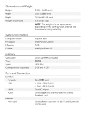
System Information Computer model Processor L3 cache Chipset Inspiron 3137 Intel Mobile Celeron 2 MB Intel Lynx Point-LP Memory Connector Type Speed Configurations supported One SODIMM connector DDR3L 1600 MHz 2 GB and 4 GB Ports and Connectors External: Network USB HDMI Audio Internal: Mini-card One RJ45 port • One USB 2.0 port • Two USB 3.0 ports One HDMI port One headphone and microphone combo (headset) port One half mini-card slot for Wi-Fi and Bluetooth combo card Dimensions and...
System Information Computer model Processor L3 cache Chipset Inspiron 3137 Intel Mobile Celeron 2 MB Intel Lynx Point-LP Memory Connector Type Speed Configurations supported One SODIMM connector DDR3L 1600 MHz 2 GB and 4 GB Ports and Connectors External: Network USB HDMI Audio Internal: Mini-card One RJ45 port • One USB 2.0 port • Two USB 3.0 ports One HDMI port One headphone and microphone combo (headset) port One half mini-card slot for Wi-Fi and Bluetooth combo card Dimensions and...
Specifications
Page 4
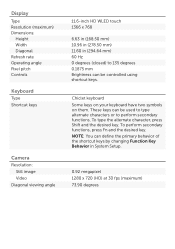
... the primary behavior of the shortcut keys by changing Function Key Behavior in (294.64 mm) 60 Hz 0 degrees (closed) to 135 degrees 0.1875 mm Brightness can be controlled using shortcut keys. Display Type Resolution (maximum) Dimensions: Height Width Diagonal Refresh rate Operating angle Pixel pitch Controls Keyboard Type Shortcut keys Camera Resolution: Still image Video Diagonal viewing angle 11.6-inch HD WLED touch 1366 x 768 6.63 in (168...
... the primary behavior of the shortcut keys by changing Function Key Behavior in (294.64 mm) 60 Hz 0 degrees (closed) to 135 degrees 0.1875 mm Brightness can be controlled using shortcut keys. Display Type Resolution (maximum) Dimensions: Height Width Diagonal Refresh rate Operating angle Pixel pitch Controls Keyboard Type Shortcut keys Camera Resolution: Still image Video Diagonal viewing angle 11.6-inch HD WLED touch 1366 x 768 6.63 in (168...


