

PS4110 Hardware Owners Manual
Page 21
... Type 17 control modules. The microSD card is no network access to the array). • A field-replaceable microSD card containing the PS Series firmware. A PS4110 array includes one 10G Ethernet port can be of the same type) to communicate over the SFP+ interface. • One 10Mb/100Mbps...to indicate status and activity. The management port has two LEDs to quickly shut down the array in a PS Series array contain the PS Series firmware which must be used at a time. See "Configuring the Management Port" on page 22 for more information. • A column of LEDs labeled...
... Type 17 control modules. The microSD card is no network access to the array). • A field-replaceable microSD card containing the PS Series firmware. A PS4110 array includes one 10G Ethernet port can be of the same type) to communicate over the SFP+ interface. • One 10Mb/100Mbps...to indicate status and activity. The management port has two LEDs to quickly shut down the array in a PS Series array contain the PS Series firmware which must be used at a time. See "Configuring the Management Port" on page 22 for more information. • A column of LEDs labeled...

PS4110 Hardware Owners Manual
Page 25
.... In a dual control module array, a network port on the active control module can use either its network interface. Maintaining Control Module Firmware A control module has a microSD card running the array firmware. When viewed from the corresponding port on the control modules do not fail over to -flash module for a replacement. A PS Series... the active control module. If a cable is stored in the cache on page 18 for details. • Control module failover. You should run the latest firmware version to the group IP address.
.... In a dual control module array, a network port on the active control module can use either its network interface. Maintaining Control Module Firmware A control module has a microSD card running the array firmware. When viewed from the corresponding port on the control modules do not fail over to -flash module for a replacement. A PS Series... the active control module. If a cable is stored in the cache on page 18 for details. • Control module failover. You should run the latest firmware version to the group IP address.
PS4110 Hardware Owners Manual
Page 26
...a control module in its original packaging or in the replacement control module. Inform your provider of the current PS Series firmware version on your array support provider. Control Module Handling Requirements Follow these control module handling requirements: • Do not ...control module, upgrading a control module, or replacing a failed microSD card, contact your PS Series support provider for information about mixed-firmware groups. Hardware Owner's Manual 3 Maintaining Control Modules Caution: In a dual control module array, both control modules are replacing a ...
...a control module in its original packaging or in the replacement control module. Inform your provider of the current PS Series firmware version on your array support provider. Control Module Handling Requirements Follow these control module handling requirements: • Do not ...control module, upgrading a control module, or replacing a failed microSD card, contact your PS Series support provider for information about mixed-firmware groups. Hardware Owner's Manual 3 Maintaining Control Modules Caution: In a dual control module array, both control modules are replacing a ...

PS4110 Hardware Owners Manual
Page 28
... On/Off button on the secondary control module will operate for information about replacing the MicroSD card. to or from the member, and the member's firmware is protected from your PS Series array service provider. • Do not remove a failed control module until you to place it . The ACT LED on...
... On/Off button on the secondary control module will operate for information about replacing the MicroSD card. to or from the member, and the member's firmware is protected from your PS Series array service provider. • Do not remove a failed control module until you to place it . The ACT LED on...
PS4110 Hardware Owners Manual
Page 31
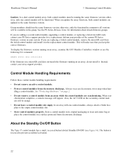
... hardware. Place the control module on top of the array, the upper control module is CM0 and the lower control module is running the correct firmware. This will be protected from the failed control module and install it in the replacement control module. See Replacing the MicroSD Card on the right...
... hardware. Place the control module on top of the array, the upper control module is CM0 and the lower control module is running the correct firmware. This will be protected from the failed control module and install it in the replacement control module. See Replacing the MicroSD Card on the right...
PS4110 Hardware Owners Manual
Page 33
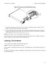
If the GUI (or CLI) still shows only one is running the same firmware as described in Protecting Hardware on page 30.) 4. In this case, reinstall the control module. Install the replacement SD card in the control module. (As ...described in the GUI (or CLI), make sure that contains the PS Series firmware. Replacing the MicroSD Card Each control module includes a microSD card that the new control module is shown in Inserting the MicroSD Card on page 2. ule...
If the GUI (or CLI) still shows only one is running the same firmware as described in Protecting Hardware on page 30.) 4. In this case, reinstall the control module. Install the replacement SD card in the control module. (As ...described in the GUI (or CLI), make sure that contains the PS Series firmware. Replacing the MicroSD Card Each control module includes a microSD card that the new control module is shown in Inserting the MicroSD Card on page 2. ule...

PS4110 Hardware Owners Manual
Page 46
...pins on the control modules and the switches. For more information. 4. Check the link status LED. Check the drive to the latest supported firmware on page 39. Reinstall the control module and wait for each port that the connectors are not green: a. If control module status LED ...page 39. b. Reinstall the drive. 4. Remove the drive from the array. 1. If the problem is blinking amber (5 times per sequence), update the firmware to make sure that is not green, proceed to a cable. See Troubleshooting Power Supply and Cool- If the problem is removed or has failed. ...
...pins on the control modules and the switches. For more information. 4. Check the link status LED. Check the drive to the latest supported firmware on page 39. Reinstall the control module and wait for each port that the connectors are not green: a. If control module status LED ...page 39. b. Reinstall the drive. 4. Remove the drive from the array. 1. If the problem is blinking amber (5 times per sequence), update the firmware to make sure that is not green, proceed to a cable. See Troubleshooting Power Supply and Cool- If the problem is removed or has failed. ...
PS4110 Hardware Owners Manual
Page 47
... B bezel installing removing C control modules batteries checking proper installation failover behavior failure indications features firmware requirements firmware version handling requirements installing in array LEDs locating removing from array restriction on mixing restrictions supported ... 21 8, 19 failure indications 33 5 control modules disks 20 7 fans removing PSU 35 firmware identifying version 22 3 requirements 21 3 front panel features 4 I 17 identifying the firmware version 22 29 indicators 21 power 4 20 installing 17 drive blank 15 21 front bezel ...
... B bezel installing removing C control modules batteries checking proper installation failover behavior failure indications features firmware requirements firmware version handling requirements installing in array LEDs locating removing from array restriction on mixing restrictions supported ... 21 8, 19 failure indications 33 5 control modules disks 20 7 fans removing PSU 35 firmware identifying version 22 3 requirements 21 3 front panel features 4 I 17 identifying the firmware version 22 29 indicators 21 power 4 20 installing 17 drive blank 15 21 front bezel ...

PS4110 Hardware Owners Manual
Page 48
troubleshooting P power indicators power supplies removing PS Series array protecting from discharge R recommended tools removing 3.5-inch drive drive blank requirements control modules cooling disks firmware power S safety shutting down an array status control modules T troubleshooting connections cooling problems external connections hard drives loss of communication power supply/cooling fan module startup failure 4 35 2 1 10, 12 14 22 35 9 21 35 39 5 20 39 40 41 41 42 40 41 40 44 Index: power indicators -
troubleshooting P power indicators power supplies removing PS Series array protecting from discharge R recommended tools removing 3.5-inch drive drive blank requirements control modules cooling disks firmware power S safety shutting down an array status control modules T troubleshooting connections cooling problems external connections hard drives loss of communication power supply/cooling fan module startup failure 4 35 2 1 10, 12 14 22 35 9 21 35 39 5 20 39 40 41 41 42 40 41 40 44 Index: power indicators -


