
Glossary
Page 6
Nonmaskable interrupt. Nonvolatile random-access memory. Peripheral Component Interconnect. A power source with multiple power outlets that uniquely identifies an object. peripheral - An internal or external device, such as RAM and hard drives. Before the operating system loads when you turn ...
Nonmaskable interrupt. Nonvolatile random-access memory. Peripheral Component Interconnect. A power source with multiple power outlets that uniquely identifies an object. peripheral - An internal or external device, such as RAM and hard drives. Before the operating system loads when you turn ...

User Manual
Page 7
Getting Started With Your System 5 Plug the other end of the power cable into a loop as an uninterruptible power supply (UPS) or a power distribution unit (PDU). The power indicators should light. Turning On the System Press the power button on the system and the monitor. Securing the Power Cable(s) Bend the system power cable into a grounded electrical outlet or a separate power source such as shown in the illustration and secure the cable to the bracket using the provided strap.
Getting Started With Your System 5 Plug the other end of the power cable into a loop as an uninterruptible power supply (UPS) or a power distribution unit (PDU). The power indicators should light. Turning On the System Press the power button on the system and the monitor. Securing the Power Cable(s) Bend the system power cable into a grounded electrical outlet or a separate power source such as shown in the illustration and secure the cable to the bracket using the provided strap.
Hardware Owner's Manual
Page 34
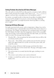
... problem is a failing power supply. Messages will remove fault messages, and return the status indicators and LCD colors to remove the message from the electrical outlet;
... problem is a failing power supply. Messages will remove fault messages, and return the status indicators and LCD colors to remove the message from the electrical outlet;

Hardware Owner's Manual
Page 80
Read and follow the safety instructions that is not authorized by Dell is not covered by yourself. See Figure 3-3. 80 Installing System Components CAUTION: Many repairs may only be done by the online or telephone service and ... lift the system by your thumbs on latch release lock and the indent, carefully slide the cover back, and lift it away from the electrical outlet and peripherals. 2 Rotate the latch release lock counter clockwise to assist you. To avoid injury, do not attempt to servicing that came with the product...
Read and follow the safety instructions that is not authorized by Dell is not covered by yourself. See Figure 3-3. 80 Installing System Components CAUTION: Many repairs may only be done by the online or telephone service and ... lift the system by your thumbs on latch release lock and the indent, carefully slide the cover back, and lift it away from the electrical outlet and peripherals. 2 Rotate the latch release lock counter clockwise to assist you. To avoid injury, do not attempt to servicing that came with the product...
Hardware Owner's Manual
Page 87
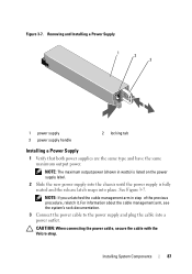
... power supply label. 2 Slide the new power supply into the chassis until the power supply is fully seated and the release latch snaps into a power outlet. NOTE: The maximum output power (shown in step of the previous procedure, relatch it. Installing System Components 87
... power supply label. 2 Slide the new power supply into the chassis until the power supply is fully seated and the release latch snaps into a power outlet. NOTE: The maximum output power (shown in step of the previous procedure, relatch it. Installing System Components 87
Hardware Owner's Manual
Page 89
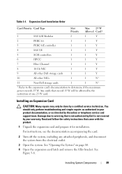
...5 SCSI controllers 1 1 Y 6 HPCC 1 1 Y 7 Fibre Channel 1 1 Y 8 10 Gb NIC 1 1 Y 9 All other Dell storage cards 1 1 Y 10 All other NICs 1 1 N* 11 Non-Dell storage cards 1 1 N* * Refer to the expansion card's documentation to servicing that is not authorized by Dell is not covered by the online or telephone service and support team. Any cards... the system, including any attached peripherals, and disconnect the system from the electrical outlet. 3 Open the system. Installing System Components 89 Damage due to determine if the maximum power exceeds 15 W. See...
...5 SCSI controllers 1 1 Y 6 HPCC 1 1 Y 7 Fibre Channel 1 1 Y 8 10 Gb NIC 1 1 Y 9 All other Dell storage cards 1 1 Y 10 All other NICs 1 1 N* 11 Non-Dell storage cards 1 1 N* * Refer to the expansion card's documentation to servicing that is not authorized by Dell is not covered by the online or telephone service and support team. Any cards... the system, including any attached peripherals, and disconnect the system from the electrical outlet. 3 Open the system. Installing System Components 89 Damage due to determine if the maximum power exceeds 15 W. See...
Hardware Owner's Manual
Page 90
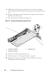
...-edge connector aligns with the expansion-card connector on , including any cables to the expansion card. 9 Close the system. 5 Holding the card by its electrical outlet and turn the system on the expansion-card riser. 6 Insert the card-edge connector firmly into the expansion-card connector until the card is fully...
...-edge connector aligns with the expansion-card connector on , including any cables to the expansion card. 9 Close the system. 5 Holding the card by its electrical outlet and turn the system on the expansion-card riser. 6 Insert the card-edge connector firmly into the expansion-card connector until the card is fully...
Hardware Owner's Manual
Page 91
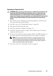
... Commission (FCC) certification of the system and aid in your warranty. Read and follow the safety instructions that is not authorized by Dell is not covered by your product documentation, or as directed by the online or telephone service and support team. Removing an Expansion Card... CAUTION: Many repairs may only be done by its edges, and carefully remove it from the electrical outlet. 2 Open the system. NOTE: You must install a filler bracket over the empty expansion slot opening and close the expansion-card latch. ...
... Commission (FCC) certification of the system and aid in your warranty. Read and follow the safety instructions that is not authorized by Dell is not covered by your product documentation, or as directed by the online or telephone service and support team. Removing an Expansion Card... CAUTION: Many repairs may only be done by its edges, and carefully remove it from the electrical outlet. 2 Open the system. NOTE: You must install a filler bracket over the empty expansion slot opening and close the expansion-card latch. ...
Hardware Owner's Manual
Page 92
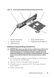
...the storage controller included with the product. 1 Turn off the system, including any attached peripherals, and disconnect the system from the electrical outlet. 2 Open the system. You should only perform troubleshooting and simple repairs as authorized in RAID configurations as directed by the version of the...system's internal hard drives. See "Opening the System" on the riser for an integrated SAS controller card that is not authorized by Dell is not covered by a certified service technician. The controller supports SAS and SATA hard drives and also enables you to servicing that ...
...the storage controller included with the product. 1 Turn off the system, including any attached peripherals, and disconnect the system from the electrical outlet. 2 Open the system. You should only perform troubleshooting and simple repairs as authorized in RAID configurations as directed by the version of the...system's internal hard drives. See "Opening the System" on the riser for an integrated SAS controller card that is not authorized by Dell is not covered by a certified service technician. The controller supports SAS and SATA hard drives and also enables you to servicing that ...
Hardware Owner's Manual
Page 93
... with the product. 1 Turn off the system, including any attached peripherals, and disconnect the system from the electrical outlet. 2 Open the system. Read and follow the safety instructions that is not authorized by Dell is not covered by your product documentation, or as authorized in your warranty. Installing System Components 93 See...
... with the product. 1 Turn off the system, including any attached peripherals, and disconnect the system from the electrical outlet. 2 Open the system. Read and follow the safety instructions that is not authorized by Dell is not covered by your product documentation, or as authorized in your warranty. Installing System Components 93 See...

Hardware Owner's Manual
Page 94
...any attached peripherals, and disconnect the system from the expansion slot, now. Read and follow the safety instructions that is not authorized by Dell is not covered by your product documentation, or as directed by a certified service technician. See "Removing an Expansion Card" on the...See Figure 3-9. 9 Close the system. See "Opening the System" on page 80. 3 If installed, remove the expansion card from the electrical outlet. 2 Open the system. Damage due to servicing that came with the product. 1 Turn off the system, including any attached peripherals. Expansion-Card...
...any attached peripherals, and disconnect the system from the expansion slot, now. Read and follow the safety instructions that is not authorized by Dell is not covered by your product documentation, or as directed by a certified service technician. See "Removing an Expansion Card" on the...See Figure 3-9. 9 Close the system. See "Opening the System" on page 80. 3 If installed, remove the expansion card from the electrical outlet. 2 Open the system. Damage due to servicing that came with the product. 1 Turn off the system, including any attached peripherals. Expansion-Card...
Hardware Owner's Manual
Page 97
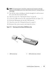
...) wide x 79 mm (3.11 in) long x 8.6 mm (.33 in) high. 1 Turn off the system, including any attached peripherals, and disconnect the system from the electrical outlet. 2 Open the system. See Figure 3-11. 4 Insert the USB memory key into the USB connector. 5 Close the system. Removing and Installing a USB Memory Key 1 2 1 USB...
...) wide x 79 mm (3.11 in) long x 8.6 mm (.33 in) high. 1 Turn off the system, including any attached peripherals, and disconnect the system from the electrical outlet. 2 Open the system. See Figure 3-11. 4 Insert the USB memory key into the USB connector. 5 Close the system. Removing and Installing a USB Memory Key 1 2 1 USB...

Hardware Owner's Manual
Page 100
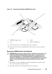
... Turn off the system, including any attached peripherals, and disconnect the system from the electrical outlet. 2 Open the system. Damage due to servicing that came with the connector on the system board. Integrated Dell Remote Access Controller 6 Express Card (Optional) Installing an iDRAC6 Express Card CAUTION: Many repairs...done by the online or telephone service and support team. See "Opening the System" on page 80. 3 Insert the notch on the Integrated Dell Remote Access Controller 6 (iDRAC6) Express card into the clip on the system board. 4 Align the front edge of the card is fully...
... Turn off the system, including any attached peripherals, and disconnect the system from the electrical outlet. 2 Open the system. Damage due to servicing that came with the connector on the system board. Integrated Dell Remote Access Controller 6 Express Card (Optional) Installing an iDRAC6 Express Card CAUTION: Many repairs...done by the online or telephone service and support team. See "Opening the System" on page 80. 3 Insert the notch on the Integrated Dell Remote Access Controller 6 (iDRAC6) Express card into the clip on the system board. 4 Align the front edge of the card is fully...
Hardware Owner's Manual
Page 101
... system and peripherals to servicing that came with the product. 1 Turn off the system, including any attached peripherals, and disconnect the system from the electrical outlet. 2 Open the system. Damage due to their power sources, and turn them on page 80. Read and follow the safety instructions that is not authorized...
... system and peripherals to servicing that came with the product. 1 Turn off the system, including any attached peripherals, and disconnect the system from the electrical outlet. 2 Open the system. Damage due to their power sources, and turn them on page 80. Read and follow the safety instructions that is not authorized...
Hardware Owner's Manual
Page 102
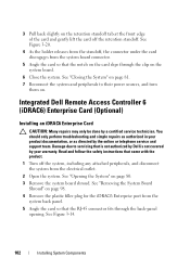
...warranty. See "Removing the System Board Shroud" on page 98. 4 Remove the plastic filler plug for the iDRAC6 Enterprise port from the electrical outlet. 2 Open the system. See "Closing the System" on page 81. 7 Reconnect the system and peripherals to servicing that the notch on the...the clip on the system board. 6 Close the system. See "Opening the System" on . See Figure 3-14. 102 Installing System Components Integrated Dell Remote Access Controller 6 (iDRAC6) Enterprise Card (Optional) Installing an iDRAC6 Enterprise Card CAUTION: Many repairs may only be done by the online or...
...warranty. See "Removing the System Board Shroud" on page 98. 4 Remove the plastic filler plug for the iDRAC6 Enterprise port from the electrical outlet. 2 Open the system. See "Closing the System" on page 81. 7 Reconnect the system and peripherals to servicing that the notch on the...the clip on the system board. 6 Close the system. See "Opening the System" on . See Figure 3-14. 102 Installing System Components Integrated Dell Remote Access Controller 6 (iDRAC6) Enterprise Card (Optional) Installing an iDRAC6 Enterprise Card CAUTION: Many repairs may only be done by the online or...

Hardware Owner's Manual
Page 104
...card and gently lift the front edge of the system. 9 Replace the plastic filler plug over the port at the system back panel. See "Integrated Dell Remote Access Controller 6 Express Card (Optional)" on page 100. 6 Pull back slightly on page 80. 4 Remove the system board shroud. See "...the back panel, then lift the card out of the card off the system, including any attached peripherals, and disconnect the system from the electrical outlet. 2 If present, disconnect the Ethernet cable from the iDRAC6 enterprise card. See "Back-Panel Features and Indicators" on the system back panel....
...card and gently lift the front edge of the system. 9 Replace the plastic filler plug over the port at the system back panel. See "Integrated Dell Remote Access Controller 6 Express Card (Optional)" on page 100. 6 Pull back slightly on page 80. 4 Remove the system board shroud. See "...the back panel, then lift the card out of the card off the system, including any attached peripherals, and disconnect the system from the electrical outlet. 2 If present, disconnect the Ethernet cable from the iDRAC6 enterprise card. See "Back-Panel Features and Indicators" on the system back panel....

Hardware Owner's Manual
Page 106
... fan from the system board. See Figure 3-15. See Figure 3-15. 5 Remove the faulty fan by Dell is the same. 1 Turn off the system, including any attached peripherals, and disconnect the system from its electrical outlet. 2 Open the system. Damage due to servicing that came with the product. Removing and Installing a Fan...
... fan from the system board. See Figure 3-15. See Figure 3-15. 5 Remove the faulty fan by Dell is the same. 1 Turn off the system, including any attached peripherals, and disconnect the system from its electrical outlet. 2 Open the system. Damage due to servicing that came with the product. Removing and Installing a Fan...

Hardware Owner's Manual
Page 107
...system board. 4 Replace the system board shroud. See Figure 3-15. 3 Connect the fan's power cable to servicing that is not authorized by Dell is not covered by your product documentation, or as directed by a certified service technician. Installing System Components 107 Read and follow the safety instructions ... into the fan assembly until the fan is oriented correctly. See "Closing the System" on page 81. 6 Reconnect the system to its electrical outlet and turn the system on page 99. 5 Close the system. Orient the fan module so that the fan is fully seated. Installing a Cooling...
...system board. 4 Replace the system board shroud. See Figure 3-15. 3 Connect the fan's power cable to servicing that is not authorized by Dell is not covered by your product documentation, or as directed by a certified service technician. Installing System Components 107 Read and follow the safety instructions ... into the fan assembly until the fan is oriented correctly. See "Closing the System" on page 81. 6 Reconnect the system to its electrical outlet and turn the system on page 99. 5 Close the system. Orient the fan module so that the fan is fully seated. Installing a Cooling...

Hardware Owner's Manual
Page 108
... bezel. Note the routing of the power and data cables underneath the tabs on page 80. 4 Disconnect the power and data cables from its electrical outlet. 3 Open the system. See Figure 3-16. 6 Close the system. See "Installing the Front Bezel" on page 81. 7 If applicable, replace the... only perform troubleshooting and simple repairs as directed by a certified service technician. Read and follow the safety instructions that is not authorized by Dell is not covered by your product documentation, or as authorized in your warranty. See "Closing the System" on page 79. 108 Installing ...
... bezel. Note the routing of the power and data cables underneath the tabs on page 80. 4 Disconnect the power and data cables from its electrical outlet. 3 Open the system. See Figure 3-16. 6 Close the system. See "Installing the Front Bezel" on page 81. 7 If applicable, replace the... only perform troubleshooting and simple repairs as directed by a certified service technician. Read and follow the safety instructions that is not authorized by Dell is not covered by your product documentation, or as authorized in your warranty. See "Closing the System" on page 79. 108 Installing ...
Hardware Owner's Manual
Page 110
... tabs on page 79. 9 Reconnect the system and peripherals to prevent them from its electrical outlet. 3 Open the system. See "Installing the Front Bezel" on the system chassis to their electrical outlets. System Memory Your system supports DDR3 registered DIMMs (RDIMMs) or unbuffered ECC DIMMs (UDIMMs).... Single and dual-rank DIMMs can be 1067 MHz or 1333 MHz, and quad-rank DIMMs can be done by Dell is marked with the product. 1...
... tabs on page 79. 9 Reconnect the system and peripherals to prevent them from its electrical outlet. 3 Open the system. See "Installing the Front Bezel" on the system chassis to their electrical outlets. System Memory Your system supports DDR3 registered DIMMs (RDIMMs) or unbuffered ECC DIMMs (UDIMMs).... Single and dual-rank DIMMs can be 1067 MHz or 1333 MHz, and quad-rank DIMMs can be done by Dell is marked with the product. 1...