Setup Guide
Page 4
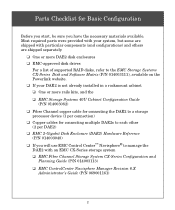
..., and the ❑ EMC Storage Systems 40U Cabinet Configuration Guide (P/N 014003082) ❑ Fibre Channel copper cable for connecting the DAE2 to manage the DAE2 with an EMC CX-Series storage system ❑ EMC Fibre Channel Storage System CX-Series Configuration and Planning ...) ❑ EMC ControlCenter Navisphere Manager Revision 6.X Administrator's Guide (P/N 069001161) 2 Parts Checklist for connecting multiple DAE2s to each other (2 per connection) ❑ Copper cables for Basic Configuration Before you start, be sure you will use EMC Control Center™ Navisphere® to...
..., and the ❑ EMC Storage Systems 40U Cabinet Configuration Guide (P/N 014003082) ❑ Fibre Channel copper cable for connecting the DAE2 to manage the DAE2 with an EMC CX-Series storage system ❑ EMC Fibre Channel Storage System CX-Series Configuration and Planning ...) ❑ EMC ControlCenter Navisphere Manager Revision 6.X Administrator's Guide (P/N 069001161) 2 Parts Checklist for connecting multiple DAE2s to each other (2 per connection) ❑ Copper cables for Basic Configuration Before you start, be sure you will use EMC Control Center™ Navisphere® to...
Setup Guide
Page 5
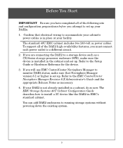
...and set up . If your DAE2s. 1. To support all of the DAE2 high-availability features, you must connect each power outlet to a storage device such as necessary. 4. The standard 40U EMC cabinet includes two 240-volt ac power cables. If you are connecting the DAE2 to a different circuit. 2. ...If you will use EMC ControlCenter Navisphere Manager to monitor DAE2 status, make sure the device is set up. You can add DAE2 enclosures to the Setup Guide or Hardware ...
...and set up . If your DAE2s. 1. To support all of the DAE2 high-availability features, you must connect each power outlet to a storage device such as necessary. 4. The standard 40U EMC cabinet includes two 240-volt ac power cables. If you are connecting the DAE2 to a different circuit. 2. ...If you will use EMC ControlCenter Navisphere Manager to monitor DAE2 status, make sure the device is set up. You can add DAE2 enclosures to the Setup Guide or Hardware ...
Setup Guide
Page 6
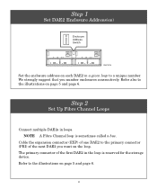
...the storage device. Refer to a unique number. Step 2 Set Up Fibre Channel Loops Connect multiple DAE2s in a given loop to the illustrations on page 5 and page 6. Cable the expansion connector (EXP) of one DAE2 to the illustrations on page 5 and page 6. 4 Refer also to the primary connector (PRI)... of the first DAE2 in the loop is sometimes called a bus. We strongly suggest that you want on each DAE2 in loops. The primary...
...the storage device. Refer to a unique number. Step 2 Set Up Fibre Channel Loops Connect multiple DAE2s in a given loop to the illustrations on page 5 and page 6. Cable the expansion connector (EXP) of one DAE2 to the illustrations on page 5 and page 6. 4 Refer also to the primary connector (PRI)... of the first DAE2 in the loop is sometimes called a bus. We strongly suggest that you want on each DAE2 in loops. The primary...
Setup Guide
Page 9
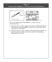
Plug the other FC device EMC2312 1. Refer to a storage processing device a. Plug one end of the cables into the primary (PRI) High Speed Serial Data Connector (HSSDC) connector on the storage device. b. If you are connecting the first DAE2 in the DAE2. Step 3 Connect the DAE2 to a Storage Processing Device PRI Connector To other end of a copper cable into the appropriate connector on each Link Control Card (LCC) in a loop to the Setup Guide or the Hardware Reference for the device. 7
Plug the other FC device EMC2312 1. Refer to a storage processing device a. Plug one end of the cables into the primary (PRI) High Speed Serial Data Connector (HSSDC) connector on the storage device. b. If you are connecting the first DAE2 in the DAE2. Step 3 Connect the DAE2 to a Storage Processing Device PRI Connector To other end of a copper cable into the appropriate connector on each Link Control Card (LCC) in a loop to the Setup Guide or the Hardware Reference for the device. 7
Setup Guide
Page 10
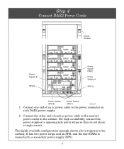
... available configuration example shown above supports write caching. Connect the other end of an ac power cable to the power connector on each ac power cable to the nearest power outlet in the cabinet. Connect one end of each DAE2 power supply. 2. It has two power strips and an SPE, and the first...
... available configuration example shown above supports write caching. Connect the other end of an ac power cable to the power connector on each ac power cable to the nearest power outlet in the cabinet. Connect one end of each DAE2 power supply. 2. It has two power strips and an SPE, and the first...
Setup Guide
Page 11
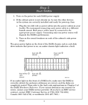
... installed and ready for each of the DAE2 Hardware Reference. Step 5 Start DAE2s 1. b. The green power lights on the front of a DAE2 is lit, make sure the DAE2 is on; Turn on each power cable to the appropriate power supply. Both power cables must be sure the other devices in ... then a. If the cabinet power is not already on each DAE2 power supply. 2. Connecting only one power source will degrade the DAE2's performance. Plug the two 240-volt ac power cables into the power outlets in your DAE2 service provider. (If you cannot determine any reasons for errors,...
... installed and ready for each of the DAE2 Hardware Reference. Step 5 Start DAE2s 1. b. The green power lights on the front of a DAE2 is lit, make sure the DAE2 is on; Turn on each power cable to the appropriate power supply. Both power cables must be sure the other devices in ... then a. If the cabinet power is not already on each DAE2 power supply. 2. Connecting only one power source will degrade the DAE2's performance. Plug the two 240-volt ac power cables into the power outlets in your DAE2 service provider. (If you cannot determine any reasons for errors,...


