Setup Guide
Page 7
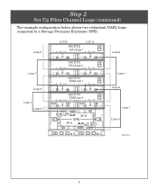
Step 2 Set Up Fibre Channel Loops (continued) The example configuration below shows two redundant DAE2 loops connected to a Storage Processor Enclosure (SPE). Loop 0 LCC B LCC A EA1/Loop 1 Loop 0 Loop 1 Loop 0 Loop 1 Loop 0 EA1/Loop 0 EA0/Loop 1 EA0/Loop 0 EXP PRI EXP PRI BE1 BE0 SP B SPE SP A BE0 BE1 Loop 1 Loop 0 Loop 1 Loop 0 EMC2311 5
Step 2 Set Up Fibre Channel Loops (continued) The example configuration below shows two redundant DAE2 loops connected to a Storage Processor Enclosure (SPE). Loop 0 LCC B LCC A EA1/Loop 1 Loop 0 Loop 1 Loop 0 Loop 1 Loop 0 EA1/Loop 0 EA0/Loop 1 EA0/Loop 0 EXP PRI EXP PRI BE1 BE0 SP B SPE SP A BE0 BE1 Loop 1 Loop 0 Loop 1 Loop 0 EMC2311 5
Setup Guide
Page 8
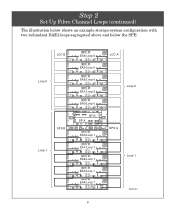
LCC B Loop 0 SPS B Loop 1 EA4/Loop 0 LCC A EA3/Loop 0 EA2/Loop 0 EA1/Loop 0 Loop 0 EA0/Loop 0 SP B SP A EA0/Loop 1 SPS A EA1/Loop 1 EA2/Loop 1 Loop 1 EA3/Loop 1 EA4/Loop 1 EXP PRI EMC2351 6 Step 2 Set Up Fibre Channel Loops (continued) The illustration below shows an example storage-system configuration with two redundant DAE2 loops segregated above and below the SPE.
LCC B Loop 0 SPS B Loop 1 EA4/Loop 0 LCC A EA3/Loop 0 EA2/Loop 0 EA1/Loop 0 Loop 0 EA0/Loop 0 SP B SP A EA0/Loop 1 SPS A EA1/Loop 1 EA2/Loop 1 Loop 1 EA3/Loop 1 EA4/Loop 1 EXP PRI EMC2351 6 Step 2 Set Up Fibre Channel Loops (continued) The illustration below shows an example storage-system configuration with two redundant DAE2 loops segregated above and below the SPE.
Setup Guide
Page 9
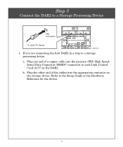
Refer to a storage processing device a. Plug one end of the cables into the primary (PRI) High Speed Serial Data Connector (HSSDC) connector on the storage device. b. Step 3 Connect the DAE2 to a Storage Processing Device PRI Connector To other end of a copper cable into the appropriate connector on each Link Control Card (LCC) in a loop to the Setup Guide or the Hardware Reference for the device. 7 Plug the other FC device EMC2312 1. If you are connecting the first DAE2 in the DAE2.
Refer to a storage processing device a. Plug one end of the cables into the primary (PRI) High Speed Serial Data Connector (HSSDC) connector on the storage device. b. Step 3 Connect the DAE2 to a Storage Processing Device PRI Connector To other end of a copper cable into the appropriate connector on each Link Control Card (LCC) in a loop to the Setup Guide or the Hardware Reference for the device. 7 Plug the other FC device EMC2312 1. If you are connecting the first DAE2 in the DAE2.