Troubleshooting Guide
Page 3
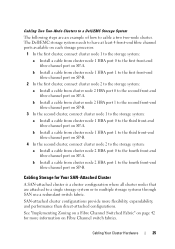
... Other Documents You May Need 13 2 Cabling Your Cluster Hardware 15 Cabling the Mouse, Keyboard, and Monitor 15 Cabling the Power Supplies 15 Cabling Your Cluster for Public and Private Networks 17 Cabling the Public Network 18 Cabling the Private Network 19 NIC Teaming 19 Cabling the Storage Systems 19 Cabling Storage for Your Direct-Attached Cluster 20...
... Other Documents You May Need 13 2 Cabling Your Cluster Hardware 15 Cabling the Mouse, Keyboard, and Monitor 15 Cabling the Power Supplies 15 Cabling Your Cluster for Public and Private Networks 17 Cabling the Public Network 18 Cabling the Private Network 19 NIC Teaming 19 Cabling the Storage Systems 19 Cabling Storage for Your Direct-Attached Cluster 20...
Troubleshooting Guide
Page 12
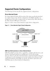
...load balancing between multiple ports on each storage processor in the storage system. Because of the cluster are connected by Dell connect to the Fibre Channel HBA ports in a direct-attached configuration. 12 Introduction Supported Cluster Configurations The following sections... describe the supported cluster configurations. However, the direct-attached clusters supported by cables directly to a single port on the same storage processor. In this configuration, the RAID controllers (or storage processors) ...
...load balancing between multiple ports on each storage processor in the storage system. Because of the cluster are connected by Dell connect to the Fibre Channel HBA ports in a direct-attached configuration. 12 Introduction Supported Cluster Configurations The following sections... describe the supported cluster configurations. However, the direct-attached clusters supported by cables directly to a single port on the same storage processor. In this configuration, the RAID controllers (or storage processors) ...
Troubleshooting Guide
Page 15
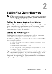
... Supplies See the documentation for each node to the switch box. Cabling Your Cluster Hardware 15 Cabling Your Cluster Hardware NOTE: To configure Dell blade server modules in a Dell PowerEdge cluster, see the Using Dell Blade Servers in your cluster solution and ensure that the specific power... systems and two storage systems. To ensure redundancy, the primary power supplies of each component in a Dell PowerEdge High Availability Cluster document located on cabling connections of all the components are grouped into one or two circuits and the redundant power supplies are ...
... Supplies See the documentation for each node to the switch box. Cabling Your Cluster Hardware 15 Cabling Your Cluster Hardware NOTE: To configure Dell blade server modules in a Dell PowerEdge cluster, see the Using Dell Blade Servers in your cluster solution and ensure that the specific power... systems and two storage systems. To ensure redundancy, the primary power supplies of each component in a Dell PowerEdge High Availability Cluster document located on cabling connections of all the components are grouped into one or two circuits and the redundant power supplies are ...
Troubleshooting Guide
Page 16
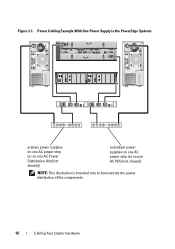
Figure 2-1. Power Cabling Example With One Power Supply in the PowerEdge Systems 1 0123 1 0123 0 0 primary power supplies on one AC power strip (or on one AC Power Distribution Unit [not shown]) redundant power supplies on one AC power strip (or on one AC PDU [not shown]) NOTE: This illustration is intended only to demonstrate the power distribution of the components. 16 Cabling Your Cluster Hardware
Figure 2-1. Power Cabling Example With One Power Supply in the PowerEdge Systems 1 0123 1 0123 0 0 primary power supplies on one AC power strip (or on one AC Power Distribution Unit [not shown]) redundant power supplies on one AC power strip (or on one AC PDU [not shown]) NOTE: This illustration is intended only to demonstrate the power distribution of the components. 16 Cabling Your Cluster Hardware

Troubleshooting Guide
Page 17
Cabling Your Cluster for Public and Private Networks The network adapters in the cluster nodes provide at support.dell.com. NOTE: To configure Dell blade server modules in a Dell PowerEdge cluster, see the Using Dell Blade Servers in a Dell PowerEdge High Availability Cluster document located on one AC power strip (or on the Dell ... power supplies on one AC PDU [not shown]) NOTE: This illustration is intended only to demonstrate the power distribution of the components. Cabling Your Cluster Hardware 17 Figure 2-2. Power Cabling Example With Two Power Supplies in Table 2-1.
Cabling Your Cluster for Public and Private Networks The network adapters in the cluster nodes provide at support.dell.com. NOTE: To configure Dell blade server modules in a Dell PowerEdge cluster, see the Using Dell Blade Servers in a Dell PowerEdge High Availability Cluster document located on one AC power strip (or on the Dell ... power supplies on one AC PDU [not shown]) NOTE: This illustration is intended only to demonstrate the power distribution of the components. Cabling Your Cluster Hardware 17 Figure 2-2. Power Cabling Example With Two Power Supplies in Table 2-1.
Troubleshooting Guide
Page 18
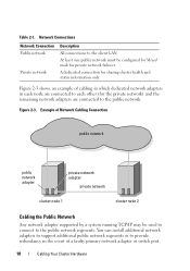
...network must be used to connect to the client LAN. Example of a faulty primary network adapter or switch port. 18 Cabling Your Cluster Hardware Table 2-1. Network Connections Network Connection Public network Private network Description All connections to the public network segments. ...Figure 2-3 shows an example of cabling in which dedicated network adapters in the event of Network Cabling Connection public network public network adapter private network adapter private network cluster node 1 cluster node 2 Cabling the Public Network Any network adapter supported by...
...network must be used to connect to the client LAN. Example of a faulty primary network adapter or switch port. 18 Cabling Your Cluster Hardware Table 2-1. Network Connections Network Connection Public network Private network Description All connections to the public network segments. ...Figure 2-3 shows an example of cabling in which dedicated network adapters in the event of Network Cabling Connection public network public network adapter private network adapter private network cluster node 1 cluster node 2 Cabling the Public Network Any network adapter supported by...
Troubleshooting Guide
Page 19
...and fault tolerance. Your cluster supports NIC teaming, only in NIC teaming. Do not mix brands in a public network. Cabling the Private Network The private network connection to the nodes is provided by a different network adapter in the nodes to a ...Hardware Components Connection Network switch Gigabit Ethernet network Connect standard Ethernet cables adapters and switches from the network adapters in each node. Cabling the Storage Systems This section provides information on cabling your cluster to -Point Copper Gigabit Ethernet Gigabit network adapters ...
...and fault tolerance. Your cluster supports NIC teaming, only in NIC teaming. Do not mix brands in a public network. Cabling the Private Network The private network connection to the nodes is provided by a different network adapter in the nodes to a ...Hardware Components Connection Network switch Gigabit Ethernet network Connect standard Ethernet cables adapters and switches from the network adapters in each node. Cabling the Storage Systems This section provides information on cabling your cluster to -Point Copper Gigabit Ethernet Gigabit network adapters ...
Troubleshooting Guide
Page 20
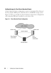
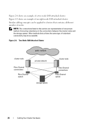
Figure 2-4 shows an example of redundant Fibre Channel host bus adapter (HBA) ports cabled directly to a Dell/EMC storage system. Direct-Attached Cluster Configuration cluster node public network private network Fibre Channel connections storage system cluster node Fibre Channel connections 20 Cabling Your Cluster Hardware Figure 2-4. Cabling Storage for Your Direct-Attached Cluster A direct-attached cluster configuration consists of a direct-attached, single cluster configuration with redundant HBA ports installed in each cluster node.
Figure 2-4 shows an example of redundant Fibre Channel host bus adapter (HBA) ports cabled directly to a Dell/EMC storage system. Direct-Attached Cluster Configuration cluster node public network private network Fibre Channel connections storage system cluster node Fibre Channel connections 20 Cabling Your Cluster Hardware Figure 2-4. Cabling Storage for Your Direct-Attached Cluster A direct-attached cluster configuration consists of a direct-attached, single cluster configuration with redundant HBA ports installed in each cluster node.
Troubleshooting Guide
Page 21
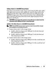
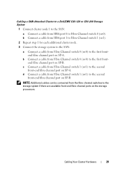
... ports available on each storage processor. 1 Connect cluster node 1 to the storage system: a Install a cable from cluster node 1 HBA port 0 to the second front-end fibre channel port on SP-A. Cabling a Cluster to a Dell/EMC Storage System Each cluster node attaches to the storage system using two Fibre optic... cables with indexed tabs that attach to the HBA ports in the cluster nodes and the storage...
... ports available on each storage processor. 1 Connect cluster node 1 to the storage system: a Install a cable from cluster node 1 HBA port 0 to the second front-end fibre channel port on SP-A. Cabling a Cluster to a Dell/EMC Storage System Each cluster node attaches to the storage system using two Fibre optic... cables with indexed tabs that attach to the HBA ports in the cluster nodes and the storage...
Troubleshooting Guide
Page 22
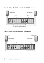
Cabling a Two-Node Cluster to a CX4-480 Storage System cluster node 1 HBA ports (2) 01 SP-B cluster node 2 HBA ports (2) 10 SP-A 1 0123 0123 1 0123 0123 0 0 CX4-480 storage system 22 Cabling Your Cluster Hardware Figure 2-5. Cabling a Two-Node Cluster to a CX4-120 or CX4-240 Storage System cluster node 1 cluster node 2 HBA ports (2) 01 SP-B HBA ports (2) 10 SP-A 1 0123 1 0123 0 0 CX4-120 or CX4-240 storage system Figure 2-6.
Cabling a Two-Node Cluster to a CX4-480 Storage System cluster node 1 HBA ports (2) 01 SP-B cluster node 2 HBA ports (2) 10 SP-A 1 0123 0123 1 0123 0123 0 0 CX4-480 storage system 22 Cabling Your Cluster Hardware Figure 2-5. Cabling a Two-Node Cluster to a CX4-120 or CX4-240 Storage System cluster node 1 cluster node 2 HBA ports (2) 01 SP-B HBA ports (2) 10 SP-A 1 0123 1 0123 0 0 CX4-120 or CX4-240 storage system Figure 2-6.
Troubleshooting Guide
Page 23
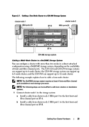
... in a direct-attached configuration using a Dell/EMC storage system, depending on each storage processor. The following steps can be modified to the first front-end fibre channel port on SP-A. Cabling a Two-Node Cluster to a CX4-960 Storage System cluster node 1 HBA ports... 01 0 1 2 3 0 1 23 10 0 1 23 0 1 23 0 1 0 1 SP-A CX4-960 storage system Cabling a Multi-Node Cluster to a Dell/EMC Storage System You can support up to cable a four-node cluster: NOTE: The Dell/EMC storage system requires at least 4 front-end fibre channel ports available on the availability...
... in a direct-attached configuration using a Dell/EMC storage system, depending on each storage processor. The following steps can be modified to the first front-end fibre channel port on SP-A. Cabling a Two-Node Cluster to a CX4-960 Storage System cluster node 1 HBA ports... 01 0 1 2 3 0 1 23 10 0 1 23 0 1 23 0 1 0 1 SP-A CX4-960 storage system Cabling a Multi-Node Cluster to a Dell/EMC Storage System You can support up to cable a four-node cluster: NOTE: The Dell/EMC storage system requires at least 4 front-end fibre channel ports available on the availability...
Troubleshooting Guide
Page 24
...end fibre channel port on SP-B. 4 Connect cluster node 4 to the storage system: a Install a cable from cluster node 4 HBA port 0 to the fourth front-end fibre channel port on Dell/EMC CX4-120 and CX4-240 storage systems allows you to connect 3 two-node clusters, or 2 two-node clusters and 2 ...attached environment. Similarly, the 12 front-end fibre channel ports per storage processor on SP-B. b Install a cable from cluster node 4 HBA port 1 to the fourth front-end fibre channel port on Dell/EMC CX4-480 storage system allows you to connect 6 two-node clusters or 5 two-node clusters and 2 non-...
...end fibre channel port on SP-B. 4 Connect cluster node 4 to the storage system: a Install a cable from cluster node 4 HBA port 0 to the fourth front-end fibre channel port on Dell/EMC CX4-120 and CX4-240 storage systems allows you to connect 3 two-node clusters, or 2 two-node clusters and 2 ...attached environment. Similarly, the 12 front-end fibre channel ports per storage processor on SP-B. b Install a cable from cluster node 4 HBA port 1 to the fourth front-end fibre channel port on Dell/EMC CX4-480 storage system allows you to connect 6 two-node clusters or 5 two-node clusters and 2 non-...
Troubleshooting Guide
Page 25
... second cluster, connect cluster node 2 to the storage system: a Install a cable from cluster node 2 HBA port 1 to the third front-end fibre channel port on Fibre Channel switch fabrics. The Dell/EMC storage system needs to have at least 4 front-end fibre channel ports ...for more flexibility, expandability, and performance than direct-attached configurations. Cabling Two Two-Node Clusters to a Dell/EMC Storage System The following steps are attached to a single storage system or to cable a two two-node cluster. b Install a cable from cluster node 1 HBA port 1 to the first front...
... second cluster, connect cluster node 2 to the storage system: a Install a cable from cluster node 2 HBA port 1 to the third front-end fibre channel port on Fibre Channel switch fabrics. The Dell/EMC storage system needs to have at least 4 front-end fibre channel ports ...for more flexibility, expandability, and performance than direct-attached configurations. Cabling Two Two-Node Clusters to a Dell/EMC Storage System The following steps are attached to a single storage system or to cable a two two-node cluster. b Install a cable from cluster node 1 HBA port 1 to the first front...
Troubleshooting Guide
Page 26
Similar cabling concepts can be applied to clusters that achieve the same type of redundant connectivity may be acceptable. Figure 2-9 shows an example of ensuring redundancy in ...-Attached Cluster public network cluster node Fibre Channel connections Fibre Channel switch private network storage system cluster node Fibre Channel connections Fibre Channel switch 26 Cabling Your Cluster Hardware Figure 2-8 shows an example of nodes.
Similar cabling concepts can be applied to clusters that achieve the same type of redundant connectivity may be acceptable. Figure 2-9 shows an example of ensuring redundancy in ...-Attached Cluster public network cluster node Fibre Channel connections Fibre Channel switch private network storage system cluster node Fibre Channel connections Fibre Channel switch 26 Cabling Your Cluster Hardware Figure 2-8 shows an example of nodes.
Troubleshooting Guide
Page 28
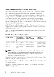
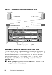
...switches and the connectors on the cluster nodes and storage systems. Each HBA port is cabled to a port on a Dell/EMC storage system. Cabling a SAN-Attached Cluster to a Dell/EMC Storage System The cluster nodes attach to the storage system using a redundant switch fabric...Cables Required CX4-120, CX4-240 Two to six ports Four to twelve CX4-480 Four to eight ports Eight to sixteen CX4-960 Four to twelve ports Eight to sixteen Cabling Description Attach one cable from each storage processor port to a CX4-960 storage system. 28 Cabling Your Cluster Hardware Storage System Cabling...
...switches and the connectors on the cluster nodes and storage systems. Each HBA port is cabled to a port on a Dell/EMC storage system. Cabling a SAN-Attached Cluster to a Dell/EMC Storage System The cluster nodes attach to the storage system using a redundant switch fabric...Cables Required CX4-120, CX4-240 Two to six ports Four to twelve CX4-480 Four to eight ports Eight to sixteen CX4-960 Four to twelve ports Eight to sixteen Cabling Description Attach one cable from each storage processor port to a CX4-960 storage system. 28 Cabling Your Cluster Hardware Storage System Cabling...
Troubleshooting Guide
Page 29
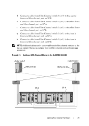
... fibre channel ports on the storage processors. NOTE: Additional cables can be connected from the fibre channel switches to the second front-end fibre channel port on SP-A. Cabling a SAN-Attached Cluster to a Dell/EMC CX4-120 or CX4-240 Storage System 1 Connect cluster node 1 to the SAN...: a Connect a cable from HBA port 0 to the first frontend fibre channel port on SP-B. b Connect a cable from Fibre Channel switch 0 (sw0) to...
... fibre channel ports on the storage processors. NOTE: Additional cables can be connected from the fibre channel switches to the second front-end fibre channel port on SP-A. Cabling a SAN-Attached Cluster to a Dell/EMC CX4-120 or CX4-240 Storage System 1 Connect cluster node 1 to the SAN...: a Connect a cable from HBA port 0 to the first frontend fibre channel port on SP-B. b Connect a cable from Fibre Channel switch 0 (sw0) to...
Troubleshooting Guide
Page 30
... to the second front-end fibre channel port on SP-A. 30 Cabling Your Cluster Hardware b Connect a cable from HBA port 0 to the first frontend fibre channel port on SP-A. Cabling a SAN-Attached Cluster to the Dell/EMC CX4-120 or CX4-240 cluster node 1 cluster node 2 HBA ports (2) 01 HBA ...ports (2) 01 sw0 SP-B sw1 SP-A 1 0123 1 0123 0 0 CX4-120 or CX4-240 storage system Cabling a SAN-Attached Cluster to the Dell/EMC CX4-480 or CX4-960 Storage System...
... to the second front-end fibre channel port on SP-A. 30 Cabling Your Cluster Hardware b Connect a cable from HBA port 0 to the first frontend fibre channel port on SP-A. Cabling a SAN-Attached Cluster to the Dell/EMC CX4-120 or CX4-240 cluster node 1 cluster node 2 HBA ports (2) 01 HBA ...ports (2) 01 sw0 SP-B sw1 SP-A 1 0123 1 0123 0 0 CX4-120 or CX4-240 storage system Cabling a SAN-Attached Cluster to the Dell/EMC CX4-480 or CX4-960 Storage System...
Troubleshooting Guide
Page 31
...front-end fibre channel port on SP-B. NOTE: Additional cables can be connected from Fibre Channel switch 1 (sw1) to the third frontend fibre channel port on SP-B. f Connect a cable from the fibre channel switches to the Dell/EMC CX4-480 cluster node 1 cluster node 2 HBA ports ...(2) 01 HBA ports (2) 01 sw0 SP-B sw1 SP-A 1 0123 0123 1 0123 0123 0 0 CX4-480 storage system Cabling Your Cluster Hardware 31
...front-end fibre channel port on SP-B. NOTE: Additional cables can be connected from Fibre Channel switch 1 (sw1) to the third frontend fibre channel port on SP-B. f Connect a cable from the fibre channel switches to the Dell/EMC CX4-480 cluster node 1 cluster node 2 HBA ports ...(2) 01 HBA ports (2) 01 sw0 SP-B sw1 SP-A 1 0123 0123 1 0123 0123 0 0 CX4-480 storage system Cabling Your Cluster Hardware 31
Troubleshooting Guide
Page 32
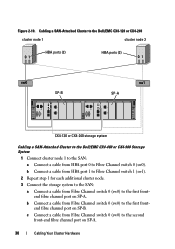
...10, Figure 2-11, and Figure 2-12 as examples for SAN-attached clusters, see the Dell Cluster Configuration Support Matrix on the processor enclosure. Cabling a SAN-Attached Cluster to the Dell\EMC CX4-960 cluster node 1 cluster node 2 HBA ports (2) 01 HBA ports (2) 01 sw0 ... SP-B Fibre Channel switch sw1 0 1 23 0 1 23 0 1 23 0 1 23 0 1 0 1 CX4-960 storage system SP-A Cabling Multiple SAN-Attached Clusters to a Dell/EMC Storage System To cable multiple clusters to the storage system, connect the cluster nodes to the appropriate Fibre Channel switches and then connect...
...10, Figure 2-11, and Figure 2-12 as examples for SAN-attached clusters, see the Dell Cluster Configuration Support Matrix on the processor enclosure. Cabling a SAN-Attached Cluster to the Dell\EMC CX4-960 cluster node 1 cluster node 2 HBA ports (2) 01 HBA ports (2) 01 sw0 ... SP-B Fibre Channel switch sw1 0 1 23 0 1 23 0 1 23 0 1 23 0 1 0 1 CX4-960 storage system SP-A Cabling Multiple SAN-Attached Clusters to a Dell/EMC Storage System To cable multiple clusters to the storage system, connect the cluster nodes to the appropriate Fibre Channel switches and then connect...

Troubleshooting Guide
Page 33
...port on SP-A. b Connect a cable from Fibre Channel switch 0 (sw0) to Fibre Channel switch 0 (sw0). NOTE: Additional cables can be connected from HBA port 0 to the first frontend fibre channel port on SP-B. Cabling Multiple SAN-Attached Clusters to the CX4-480 or CX4-960Storage System 1 In the first ...cluster, connect cluster node 1 to the SAN: a Connect a cable from the fibre channel switches to the second front-end fibre channel ...
...port on SP-A. b Connect a cable from Fibre Channel switch 0 (sw0) to Fibre Channel switch 0 (sw0). NOTE: Additional cables can be connected from HBA port 0 to the first frontend fibre channel port on SP-B. Cabling Multiple SAN-Attached Clusters to the CX4-480 or CX4-960Storage System 1 In the first ...cluster, connect cluster node 1 to the SAN: a Connect a cable from the fibre channel switches to the second front-end fibre channel ...


