Monitor Users Guide
Page 3
... Parts and Controls 11 Front View 11 Back View 12 Bottom View 13 Monitor Specifications 15 Resolution Specifications 16 Supported Video Modes 17 Preset Display Modes 17 Multi-Stream Transport (MST) Modes 18 Unified Communications (UC) Platform Compatibility List 18 Electrical Specifications 19 Webcam and Microphone Specifications 20 Speaker Specifications 20 Physical Characteristics 21 Monitor Environmental Characteristics 22 Pin Assignments 23 Universal Serial Bus (USB) Interface 26 USB Upstream Connector 26 USB Downstream Connector 27 USB Ports 27 Plug and...
... Parts and Controls 11 Front View 11 Back View 12 Bottom View 13 Monitor Specifications 15 Resolution Specifications 16 Supported Video Modes 17 Preset Display Modes 17 Multi-Stream Transport (MST) Modes 18 Unified Communications (UC) Platform Compatibility List 18 Electrical Specifications 19 Webcam and Microphone Specifications 20 Speaker Specifications 20 Physical Characteristics 21 Monitor Environmental Characteristics 22 Pin Assignments 23 Universal Serial Bus (USB) Interface 26 USB Upstream Connector 26 USB Downstream Connector 27 USB Ports 27 Plug and...
Monitor Users Guide
Page 4
... 39 Connecting Your Monitor 39 Connecting the HDMI Cable 40 Connecting the DisplayPort (DisplayPort to DisplayPort) Cable 40 Connecting the Monitor for DP Multi-Stream Transport (MST) Function 41 Using the Tilt, Swivel, and Vertical Extension 42 Tilt, Swivel 42 Vertical Extension 43 Rotating the Monitor 43 Rotate Clockwise 44 Rotate Counterclockwise 44 Adjusting the Rotation Display Settings of Your System 45 Removing the Monitor Stand 46 VESA Wall Mounting (optional...
... 39 Connecting Your Monitor 39 Connecting the HDMI Cable 40 Connecting the DisplayPort (DisplayPort to DisplayPort) Cable 40 Connecting the Monitor for DP Multi-Stream Transport (MST) Function 41 Using the Tilt, Swivel, and Vertical Extension 42 Tilt, Swivel 42 Vertical Extension 43 Rotating the Monitor 43 Rotate Clockwise 44 Rotate Counterclockwise 44 Adjusting the Rotation Display Settings of Your System 45 Removing the Monitor Stand 46 VESA Wall Mounting (optional...
Monitor Users Guide
Page 9
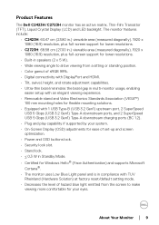
... charging ports (BC 1.2). • Plug and play capability if supported by your system. • On-Screen Display (OSD) adjustments for ease of set-up and screen optimization. • Power and OSD buttons lock. • Security lock slot. • Stand lock. • < 0.3 W in Standby Mode. • Certified for Windows Hello® (Face Authentication) and supports Microsoft Cortana®. • The monitor uses Low Blue Light panel and is in compliance with TUV Rheinland (Hardware Solution) at factory reset/default setting mode...
... charging ports (BC 1.2). • Plug and play capability if supported by your system. • On-Screen Display (OSD) adjustments for ease of set-up and screen optimization. • Power and OSD buttons lock. • Security lock slot. • Stand lock. • < 0.3 W in Standby Mode. • Certified for Windows Hello® (Face Authentication) and supports Microsoft Cortana®. • The monitor uses Low Blue Light panel and is in compliance with TUV Rheinland (Hardware Solution) at factory reset/default setting mode...
Monitor Users Guide
Page 12
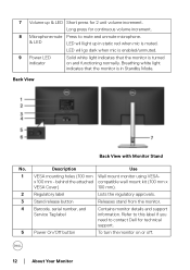
... Dell for 2 unit volume increment. Breathing white light indicates that the monitor is in static red when mic is muted. Description Use 1 VESA mounting holes (100 mm Wall mount monitor using VESA- Back View Back View with Monitor Stand No. 7 Volume up in Standby Mode. behind the attached compatible wall mount kit (100 mm x VESA Cover) 100 mm). 2 Regulatory label Lists the regulatory approvals. 3 Stand release button Releases stand from the monitor. 4 Barcode, serial number, and Service Tag label Contains monitor details and support...
... Dell for 2 unit volume increment. Breathing white light indicates that the monitor is in static red when mic is muted. Description Use 1 VESA mounting holes (100 mm Wall mount monitor using VESA- Back View Back View with Monitor Stand No. 7 Volume up in Standby Mode. behind the attached compatible wall mount kit (100 mm x VESA Cover) 100 mm). 2 Regulatory label Lists the regulatory approvals. 3 Stand release button Releases stand from the monitor. 4 Barcode, serial number, and Service Tag label Contains monitor details and support...
Monitor Users Guide
Page 13
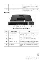
Description 1 Power connector 2 Security lock slot 3 HDMI port 4 Stand lock feature 5 DisplayPort Use Connect the power cable (shipped with your computer with the DisplayPort cable. Secures the monitor with the HDMI cable. To lock the stand to organize cables by inserting them through the slot. Connect your monitor). Bottom View without Monitor Stand No. 6 Joystick 7 Cable-management slot Bottom View Use to control the OSD menu. (For more Information, see Operating the Monitor) Use to the monitor using a M3 x 6 mm screw (screw not included). Connect your computer...
Description 1 Power connector 2 Security lock slot 3 HDMI port 4 Stand lock feature 5 DisplayPort Use Connect the power cable (shipped with your computer with the DisplayPort cable. Secures the monitor with the HDMI cable. To lock the stand to organize cables by inserting them through the slot. Connect your monitor). Bottom View without Monitor Stand No. 6 Joystick 7 Cable-management slot Bottom View Use to control the OSD menu. (For more Information, see Operating the Monitor) Use to the monitor using a M3 x 6 mm screw (screw not included). Connect your computer...
Monitor Users Guide
Page 14
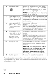
... volume control or equalizer may increase the output voltage on the headphones thereby increasing the sound pressure levels. 11 Built-in speakers To output the sound from audio input. *To avoid signal interference, when a wireless USB device has been connected to a USB downstream port, it is Type-B upstream port connected, you can use the USB connectors on the monitor. 8 SuperSpeed USB 5 Connect your USB device.* Gbps (USB 3.2 Gen1) Type-A downstream port (2) NOTE: To use...
... volume control or equalizer may increase the output voltage on the headphones thereby increasing the sound pressure levels. 11 Built-in speakers To output the sound from audio input. *To avoid signal interference, when a wireless USB device has been connected to a USB downstream port, it is Type-B upstream port connected, you can use the USB connectors on the monitor. 8 SuperSpeed USB 5 Connect your USB device.* Gbps (USB 3.2 Gen1) Type-A downstream port (2) NOTE: To use...
Monitor Users Guide
Page 19
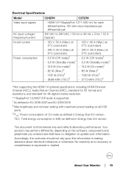
... not rely upon this information in Energy Star 8.0 version. Electrical Specifications Model C2423H C2723H Video input signals • HDMI 1.4*/DisplayPort 1.2**, 600 mV for 4K digital cinema resolution. **DisplayPort 1.2/MST/DP audio is supported. 1 As defined in EU 2019/2021 and EU 2019/2013. 2 Max brightness and contrast setting with maximum power loading on the software, components and peripherals you ordered and shall have no obligation to...
... not rely upon this information in Energy Star 8.0 version. Electrical Specifications Model C2423H C2723H Video input signals • HDMI 1.4*/DisplayPort 1.2**, 600 mV for 4K digital cinema resolution. **DisplayPort 1.2/MST/DP audio is supported. 1 As defined in EU 2019/2021 and EU 2019/2013. 2 Max brightness and contrast setting with maximum power loading on the software, components and peripherals you ordered and shall have no obligation to...

Monitor Users Guide
Page 39
... shipped with Dell supplied inbox cables. To connect your computer and disconnect the power cable. 2. Secure your monitor to work optimally with the lock. NOTE: The graphics are designed to the computer. Securing Your Monitor Using Kensington Lock (optional) The security-lock slot is located at the same time. NOTE: Do not connect all cables to a table using non-Dell cables. Appearance of illustration only. NOTE: Dell monitors are used for the...
... shipped with Dell supplied inbox cables. To connect your computer and disconnect the power cable. 2. Secure your monitor to work optimally with the lock. NOTE: The graphics are designed to the computer. Securing Your Monitor Using Kensington Lock (optional) The security-lock slot is located at the same time. NOTE: Do not connect all cables to a table using non-Dell cables. Appearance of illustration only. NOTE: Dell monitors are used for the...

Monitor Users Guide
Page 41
...: Remove the rubber plug when using DP out connector. Appearance of illustration only. If your PC Graphics Card must be certified to change the DisplayPort format settings if necessary. If it does not display an image, see Common Problems. Setting Up the Monitor │ 41 Repeat the above steps to at least DP1.2 with MST option. To make use of this feature, your monitor displays an image, installation...
...: Remove the rubber plug when using DP out connector. Appearance of illustration only. If your PC Graphics Card must be certified to change the DisplayPort format settings if necessary. If it does not display an image, see Common Problems. Setting Up the Monitor │ 41 Repeat the above steps to at least DP1.2 with MST option. To make use of this feature, your monitor displays an image, installation...

Monitor Users Guide
Page 54
... to set the video input mode to: • RGB: Select this option if your own preset color mode. Press the joystick to a computer or a media player that supports RGB output. • YCbCr: Select this option if your monitor is connected to confirm the selection. 54 │ Operating the Monitor Toggle the joystick up or down to manually adjust the color settings. Allows you to adjust the RGB color values...
... to set the video input mode to: • RGB: Select this option if your own preset color mode. Press the joystick to a computer or a media player that supports RGB output. • YCbCr: Select this option if your monitor is connected to confirm the selection. 54 │ Operating the Monitor Toggle the joystick up or down to manually adjust the color settings. Allows you to adjust the RGB color values...

Monitor Users Guide
Page 58
... monitor locked, you can also press and hold the joystick to the up or down or left or right for 4 seconds. Reset Menu • Menu Buttons: All joystick functions are locked and not accessible by the user. The default setting is locked and not accessible by the user. • Menu + Power Buttons: Both the joystick & the Power Button are locked and not accessible by -side setup. NOTE: To unlock the button...
... monitor locked, you can also press and hold the joystick to the up or down or left or right for 4 seconds. Reset Menu • Menu Buttons: All joystick functions are locked and not accessible by the user. The default setting is locked and not accessible by the user. • Menu + Power Buttons: Both the joystick & the Power Button are locked and not accessible by -side setup. NOTE: To unlock the button...

Monitor Users Guide
Page 62
... is complete when the text screen appears. When initiated, a gray screen appears. 2. The color of your warranty status, update drivers on Dell's website, etc. These are also the settings for phone support, check your monitor. Service Tag Displays the service tag of the screen changes to inspect the display in green, blue, black, white and text screens. Press the joystick. Self-Diagnostic Press the joystick to the factory default settings. To exit, press the...
... is complete when the text screen appears. When initiated, a gray screen appears. 2. The color of your warranty status, update drivers on Dell's website, etc. These are also the settings for phone support, check your monitor. Service Tag Displays the service tag of the screen changes to inspect the display in green, blue, black, white and text screens. Press the joystick. Self-Diagnostic Press the joystick to the factory default settings. To exit, press the...

Monitor Users Guide
Page 68
...; Go to http://www.dell.com/support, enter your service tag, and download the latest driver for the monitor: In Windows® 7, Windows® 8, and Windows® 8.1: 1. Depending on your graphics card website and download the latest graphic drivers. Click the dropdown list of the following OSD settings will be synchronized: Brightness, Contrast, Preset Modes, Color Temp., Custom Color (RGB Gain), Hue (Movie, Game mode), Saturation (Movie, Game mode), Response Time, and...
...; Go to http://www.dell.com/support, enter your service tag, and download the latest driver for the monitor: In Windows® 7, Windows® 8, and Windows® 8.1: 1. Depending on your graphics card website and download the latest graphic drivers. Click the dropdown list of the following OSD settings will be synchronized: Brightness, Contrast, Preset Modes, Color Temp., Custom Color (RGB Gain), Hue (Movie, Game mode), Saturation (Movie, Game mode), Response Time, and...

Monitor Users Guide
Page 80
... to the connected input signal. 4. While in this section, follow the Safety Instructions. The floating dialog box should appear on the monitor. Unplug the video cable from the back of the procedures in self-test mode, the power LED remains white. If your monitor and reconnect the video cable; then turn On both your computer and the monitor. 2. Turn on -screen (against a black background), if the monitor cannot sense a video signal and...
... to the connected input signal. 4. While in this section, follow the Safety Instructions. The floating dialog box should appear on the monitor. Unplug the video cable from the back of the procedures in self-test mode, the power LED remains white. If your monitor and reconnect the video cable; then turn On both your computer and the monitor. 2. Turn on -screen (against a black background), if the monitor cannot sense a video signal and...

Monitor Users Guide
Page 85
... in the video cable connector. • Restart the computer in the safe mode. Adjust the R/G/B value in Custom Color in Color settings OSD. • Change the Input Color Format to RGB or YCbCr/YPbPr in the Color settings OSD. • Run the built-in Color settings OSD. Synchronization Problems Safety Related Issues Intermittent Problems Missing Color Wrong Color Screen is scrambled or appears torn • Reset the monitor to factory settings. • Perform monitor self-test feature check to determine...
... in the video cable connector. • Restart the computer in the safe mode. Adjust the R/G/B value in Custom Color in Color settings OSD. • Change the Input Color Format to RGB or YCbCr/YPbPr in the Color settings OSD. • Run the built-in Color settings OSD. Synchronization Problems Safety Related Issues Intermittent Problems Missing Color Wrong Color Screen is scrambled or appears torn • Reset the monitor to factory settings. • Perform monitor self-test feature check to determine...

Monitor Users Guide
Page 86
... can be adjusted in Windows Power Options or Mac Energy Saver setting. • Alternatively, use a dynamically changing screensaver. • Plug in smal l screen, but does not the Display menu OSD. fill entire viewing area • Reset the monitor to unlock (for 4 seconds to factory settings. Check whether the OSD menu is centered on the screen Webcam/Mic does not work • USB cable not plug in or not select the correct USB source • Not set the monitor webcam/mic...
... can be adjusted in Windows Power Options or Mac Energy Saver setting. • Alternatively, use a dynamically changing screensaver. • Plug in smal l screen, but does not the Display menu OSD. fill entire viewing area • Reset the monitor to unlock (for 4 seconds to factory settings. Check whether the OSD menu is centered on the screen Webcam/Mic does not work • USB cable not plug in or not select the correct USB source • Not set the monitor webcam/mic...

Monitor Users Guide
Page 87
.../ Volume up/ Volume up/ Microphone mute) Microphone mute) not working with not working on • Call Icon to the the port, there is plugged in properly. Plug the HDMI/DisplayPort video when cable 7 seconds later. Ensure the computer is not in diagnostics. Re-plug the signal cable if necessary. • Reset the computer or video player. No Input Signal No picture, the LED when user controls light is white are pressed • Check the signal source.
.../ Volume up/ Volume up/ Microphone mute) Microphone mute) not working with not working on • Call Icon to the the port, there is plugged in properly. Plug the HDMI/DisplayPort video when cable 7 seconds later. Ensure the computer is not in diagnostics. Re-plug the signal cable if necessary. • Reset the computer or video player. No Input Signal No picture, the LED when user controls light is white are pressed • Check the signal source.

Monitor Users Guide
Page 90
... monitor. • Select the Monitor camera again in the Camera / Video setting of DELL C2423H/C2723H to 100%, the DELL C2423H/C2723H will have the same sound level as the former. Webcam cannot Could not detect connect / Webcam Monitor camera / disconnected Could not switch back to the PC camera • Reset the monitor to Factory Settings. • Turn Off the monitor, unplug the monitor power cord, replug it is connected between the monitor...
... monitor. • Select the Monitor camera again in the Camera / Video setting of DELL C2423H/C2723H to 100%, the DELL C2423H/C2723H will have the same sound level as the former. Webcam cannot Could not detect connect / Webcam Monitor camera / disconnected Could not switch back to the PC camera • Reset the monitor to Factory Settings. • Turn Off the monitor, unplug the monitor power cord, replug it is connected between the monitor...

Monitor Users Guide
Page 93
...; Switch audio device configuration of decreasing OSD Windows to the monitor. • Ensure that the USB upstream cable is provisioned / setup as 'Teams Only' mode. unplugging/plugging HDMI cable. The tenant administrator should enable the account to 'Teams Only' mode. value is normal behavior. Webcam no image Webcam no image when using 'conference software A', close the other 'conference software B'. audio has 3 ~ 5 • Wait for Business (SfB) Select 'DELL Monitor RGB Webcam' as Default Setting.
...; Switch audio device configuration of decreasing OSD Windows to the monitor. • Ensure that the USB upstream cable is provisioned / setup as 'Teams Only' mode. unplugging/plugging HDMI cable. The tenant administrator should enable the account to 'Teams Only' mode. value is normal behavior. Webcam no image Webcam no image when using 'conference software A', close the other 'conference software B'. audio has 3 ~ 5 • Wait for Business (SfB) Select 'DELL Monitor RGB Webcam' as Default Setting.

Display Manager on Mac Users Guide
Page 18
Select a target window size to split the screen to enable the split screen function on supported models. 2. Click on the PIP/PBP mode... (Picture-in-Picture/Picture-by-Picture) icon to suit your need. 18 │ Managing multiple video inputs Selecting PIP/PBP mode 1.
Select a target window size to split the screen to enable the split screen function on supported models. 2. Click on the PIP/PBP mode... (Picture-in-Picture/Picture-by-Picture) icon to suit your need. 18 │ Managing multiple video inputs Selecting PIP/PBP mode 1.


