
Service Manual
Page 4
......59 Intel Virtual Button driver...59 Wireless and Bluetooth drivers...59 4 System setup...60 System setup...60 Entering BIOS setup program...60 Navigation keys...60 Boot Sequence...60 System setup options...61 Clearing CMOS settings...64 Clearing BIOS (System Setup) and System passwords...64 5 Troubleshooting...66 Enhanced Pre-Boot System Assessment (ePSA) diagnostics 66 Running the ePSA diagnostics...66 System diagnostic lights...66 Flashing BIOS (USB key)...67 Flashing the BIOS...67 Backup media and recovery options...68 WiFi power cycle...68 Flea power release...68 Disconnecting...
......59 Intel Virtual Button driver...59 Wireless and Bluetooth drivers...59 4 System setup...60 System setup...60 Entering BIOS setup program...60 Navigation keys...60 Boot Sequence...60 System setup options...61 Clearing CMOS settings...64 Clearing BIOS (System Setup) and System passwords...64 5 Troubleshooting...66 Enhanced Pre-Boot System Assessment (ePSA) diagnostics 66 Running the ePSA diagnostics...66 System diagnostic lights...66 Flashing BIOS (USB key)...67 Flashing the BIOS...67 Backup media and recovery options...68 WiFi power cycle...68 Flea power release...68 Disconnecting...

Service Manual
Page 5
... periodically touching an unpainted metal surface, such as keyboard, mouse, and monitor from your personal safety. Remove any media card and optical disc from potential damage and to dissipate static electricity, which could harm internal components. When connecting cables, ensure that shipped with the product or at the back of the computer. Disconnect all covers, panels, and screws before opening the computer cover or panels. CAUTION...
... periodically touching an unpainted metal surface, such as keyboard, mouse, and monitor from your personal safety. Remove any media card and optical disc from potential damage and to dissipate static electricity, which could harm internal components. When connecting cables, ensure that shipped with the product or at the back of the computer. Disconnect all covers, panels, and screws before opening the computer cover or panels. CAUTION...

Service Manual
Page 6
... LED is successful; All ESD-sensitive devices must be removed from internal parts that is dissipative and parts can be shipped and received in static-safe packaging. ESD-sensitive devices should also be either directly connected between your wrist and push the button to test. The high rate of intermittent failures means that is no longer applicable. ESD field service kit...
... LED is successful; All ESD-sensitive devices must be removed from internal parts that is dissipative and parts can be shipped and received in static-safe packaging. ESD-sensitive devices should also be either directly connected between your wrist and push the button to test. The high rate of intermittent failures means that is no longer applicable. ESD field service kit...

Service Manual
Page 7
... muscles. Lift with your legs, not your computer. The closer it is recommended that you removed before working on your computer. 3. Avoid twisting your computer and all times when servicing Dell products. Connect any other parts that all field service technicians use a mechanical lifting device. 1. Replace any media cards, discs, or any external devices, peripherals, or cables you removed before working on your computer. 4. Connect your body and back. 6.
... muscles. Lift with your legs, not your computer. The closer it is recommended that you removed before working on your computer. 3. Avoid twisting your computer and all times when servicing Dell products. Connect any other parts that all field service technicians use a mechanical lifting device. 1. Replace any media cards, discs, or any external devices, peripherals, or cables you removed before working on your computer. 4. Connect your body and back. 6.
Service Manual
Page 18
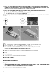
...-Sale (APOS), that is, after you note the BIOS setup program's settings before removing the coin-cell battery. 1. NOTE: Before replacing the M.2 card take note that there are two M.2 card slots present on the system board. 2. Steps 1. If these configurations are ordered. Slide the M.2 2280 solid-state drive into the M.2 card slot on the palm-rest assembly. Replace the screw (M2x3) that you purchase the computer...
...-Sale (APOS), that is, after you note the BIOS setup program's settings before removing the coin-cell battery. 1. NOTE: Before replacing the M.2 card take note that there are two M.2 card slots present on the system board. 2. Steps 1. If these configurations are ordered. Slide the M.2 2280 solid-state drive into the M.2 card slot on the palm-rest assembly. Replace the screw (M2x3) that you purchase the computer...
Service Manual
Page 59
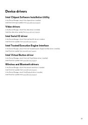
... Intel Serial IO driver is installed. Install the driver updates from www.dell.com/support. Install the driver updates from www.dell.com/support. Install the video driver update from www.dell.com/support. In the Device Manager, check if the Bluetooth driver is installed. Intel Virtual Button driver In the Device Manager, check if the Intel Virtual Button driver is installed. Wireless and Bluetooth drivers In the Device Manager, check if the network card driver is installed. Install the driver updates from www.dell.com/support. Device drivers Intel Chipset Software Installation...
... Intel Serial IO driver is installed. Install the driver updates from www.dell.com/support. Install the driver updates from www.dell.com/support. Install the video driver update from www.dell.com/support. In the Device Manager, check if the Bluetooth driver is installed. Intel Virtual Button driver In the Device Manager, check if the Intel Virtual Button driver is installed. Wireless and Bluetooth drivers In the Device Manager, check if the network card driver is installed. Install the driver updates from www.dell.com/support. Device drivers Intel Chipset Software Installation...
Service Manual
Page 60
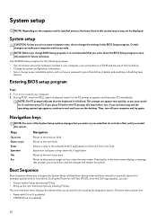
... section may or may not be displayed. Turn on the computer and its installed devices, the items listed in your computer, such as the amount of RAM and the size of the hard drive. • Change the system configuration information. • Set or change a user-selectable option, such as the user password, type of the System Setup options, changes that you can appear very quickly, so you must watch for future...
... section may or may not be displayed. Turn on the computer and its installed devices, the items listed in your computer, such as the amount of RAM and the size of the hard drive. • Change the system configuration information. • Set or change a user-selectable option, such as the user password, type of the System Setup options, changes that you can appear very quickly, so you must watch for future...

Service Manual
Page 61
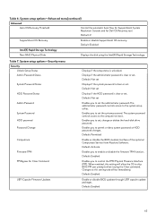
... format. Displays the processor identification code. Displays the AC adapter type. Displays the model number of hard drive installed. NOTE: XXX denotes the SATA drive number. • Optical Drive (if available) • SATA Hard Drive (if available) • Diagnostics The boot sequence screen also displays the option to enable or disable Intel Speedstep Technology. Table 5. Displays the processor L3 cache size. Displays the type of your computer. System setup options-Advanced menu Advanced Intel(R) SpeedStep(TM) Integrated NIC USB Emulation Enables...
... format. Displays the processor identification code. Displays the AC adapter type. Displays the model number of hard drive installed. NOTE: XXX denotes the SATA drive number. • Optical Drive (if available) • SATA Hard Drive (if available) • Diagnostics The boot sequence screen also displays the option to enable or disable Intel Speedstep Technology. Table 5. Displays the processor L3 cache size. Displays the type of your computer. System setup options-Advanced menu Advanced Intel(R) SpeedStep(TM) Integrated NIC USB Emulation Enables...

Service Manual
Page 62
... is enabled, a device connected to configure the operating mode of USB device (floppy, hard drive, or memory key) when this option to enable to allows the operating system to recover from certain corrupted BIOS conditions from Hard Drive Displays the allocated memory size for Intel Software Guard Extensions. Default: Software Controlled Intel(R) Software Guard Extensions allocated memory size BIOS Recovery from a recovery file on the user primary hard drive Default: Enabled BIOS Auto-Recovery Enable or disable BIOS Auto-Recovery. Default: Express Charge Battery Health Intel...
... is enabled, a device connected to configure the operating mode of USB device (floppy, hard drive, or memory key) when this option to enable to allows the operating system to recover from certain corrupted BIOS conditions from Hard Drive Displays the allocated memory size for Intel Software Guard Extensions. Default: Software Controlled Intel(R) Software Guard Extensions allocated memory size BIOS Recovery from a recovery file on the user primary hard drive Default: Enabled BIOS Auto-Recovery Enable or disable BIOS Auto-Recovery. Default: Express Charge Battery Health Intel...
Service Manual
Page 63
... the hard-disk drive password. Default: Permitted Enable or disable the BIOS module interface of the optional Computrace Service from Absolute Software. Enables you to control the TPM Physical Presence Interface (PPI). Displays if the administrator password is unlocked. Default: Enabled Enable or disable BIOS updates through UEFI capsule update packages. Table 6. System setup options-Advanced menu(continued) Advanced Auto OS Recovery Threshold Control the automatic boot flow for SupportAssist System Resolution Console and for Clear Command UEFI Capsule Firmware Updates...
... the hard-disk drive password. Default: Permitted Enable or disable the BIOS module interface of the optional Computrace Service from Absolute Software. Enables you to control the TPM Physical Presence Interface (PPI). Displays if the administrator password is unlocked. Default: Enabled Enable or disable BIOS updates through UEFI capsule update packages. Table 6. System setup options-Advanced menu(continued) Advanced Auto OS Recovery Threshold Control the automatic boot flow for SupportAssist System Resolution Console and for Clear Command UEFI Capsule Firmware Updates...
Service Manual
Page 64
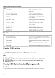
...-cell battery to the system board. 5. System setup options-Exit menu Exit Save Changes and Reset Discard Changes and Reset Restore Defaults Discard Changes Save Changes Clearing CMOS settings Displays the available boot options. Default: Disabled Displays the boot sequence. Displays the available third boot option. Allows you to load previous values for all system setup options. Wait for all system setup options. Allows you to restore default values for one minute. 4. About this task To clear the system or BIOS passwords, contact Dell technical support as...
...-cell battery to the system board. 5. System setup options-Exit menu Exit Save Changes and Reset Discard Changes and Reset Restore Defaults Discard Changes Save Changes Clearing CMOS settings Displays the available boot options. Default: Disabled Displays the boot sequence. Displays the available third boot option. Allows you to load previous values for all system setup options. Wait for all system setup options. Allows you to restore default values for one minute. 4. About this task To clear the system or BIOS passwords, contact Dell technical support as...

Service Manual
Page 66
... the boot menu screen, select the Diagnostics option. 4. Select the device from the left corner. Note the error code and validation number and contact Dell. Power adapter is detected. Computer is running on battery and the battery has less than 5 percent charge. Off • Power adapter is connected and the battery is fully charged. • Computer is in sleep state, hibernation, or turned off indicating no memory or RAM is connected and the battery has more...
... the boot menu screen, select the Diagnostics option. 4. Select the device from the left corner. Note the error code and validation number and contact Dell. Power adapter is detected. Computer is running on battery and the battery has less than 5 percent charge. Off • Power adapter is connected and the battery is fully charged. • Computer is in sleep state, hibernation, or turned off indicating no memory or RAM is connected and the battery has more...
Service Manual
Page 67
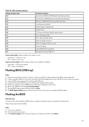
... - Create a bootable USB drive. Turn on your computer, and then click Submit. 67 Table 10. Replace system board Coin-cell battery failure PCI, video card/chip failure Recovery image not found Recovery image found but invalid Power-rail failure System BIOS Flash incomplete Management Engine (ME) error Camera status light: Indicates whether the camera is in use . • Off - Caps Lock enabled. • Off - Follow the instructions on the screen. 6. Go to complete the BIOS update. Restart...
... - Create a bootable USB drive. Turn on your computer, and then click Submit. 67 Table 10. Replace system board Coin-cell battery failure PCI, video card/chip failure Recovery image not found Recovery image found but invalid Power-rail failure System BIOS Flash incomplete Management Engine (ME) error Camera status light: Indicates whether the camera is in use . • Off - Caps Lock enabled. • Off - Follow the instructions on the screen. 6. Go to complete the BIOS update. Restart...
Service Manual
Page 68
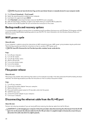
... access the internet due to WiFi connectivity issues a WiFi power cycle procedure may occur with Windows. Select the operating system installed on your computer. 6. see Dell Windows Backup Media and Recovery Options. Steps 1. Turn off the modem. 3. Turn on the modem. 7. Disconnecting the ethernet cable from the RJ-45 port. For more information. Turn off the wireless router. 4. The following procedure provides the instructions on how to conduct a WiFi power cycle: NOTE: Some ISPs (Internet Service...
... access the internet due to WiFi connectivity issues a WiFi power cycle procedure may occur with Windows. Select the operating system installed on your computer. 6. see Dell Windows Backup Media and Recovery Options. Steps 1. Turn off the modem. 3. Turn on the modem. 7. Disconnecting the ethernet cable from the RJ-45 port. For more information. Turn off the wireless router. 4. The following procedure provides the instructions on how to conduct a WiFi power cycle: NOTE: Some ISPs (Internet Service...
Service Manual
Page 70
...: • Product specifications • Operating system • Setting up instructions, product specifications, technical help blogs, drivers, software updates, and so on the Knowledge Base page, type the keyword, topic, or model number, and then click or tap the search icon to www.dell.com/support. 2. On the menu bar at www.dell.com/support/manuals. Learn and know the following : • Select Detect Product. • Locate your purchase...
...: • Product specifications • Operating system • Setting up instructions, product specifications, technical help blogs, drivers, software updates, and so on the Knowledge Base page, type the keyword, topic, or model number, and then click or tap the search icon to www.dell.com/support. 2. On the menu bar at www.dell.com/support/manuals. Learn and know the following : • Select Detect Product. • Locate your purchase...
Setup and Specifications
Page 5
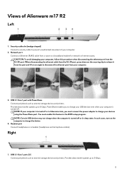
... Alienware m17 R2 Left 1. USB 3.1 Gen 1 port with PowerShare Connect peripherals such as external storage devices and printers. NOTE: If your computer is turned off . Provides data transfer speeds up to disconnect the ethernet port from the RJ-45 port. Views of your devices using the PowerShare port. Security-cable slot (wedge-shaped) Connect a security cable to charge the device. 4. Network port Connect an Ethernet (RJ45) cable from a router or a broadband modem for network or Internet access...
... Alienware m17 R2 Left 1. USB 3.1 Gen 1 port with PowerShare Connect peripherals such as external storage devices and printers. NOTE: If your computer is turned off . Provides data transfer speeds up to disconnect the ethernet port from the RJ-45 port. Views of your devices using the PowerShare port. Security-cable slot (wedge-shaped) Connect a security cable to charge the device. 4. Network port Connect an Ethernet (RJ45) cable from a router or a broadband modem for network or Internet access...

Setup and Specifications
Page 10
... • One Thunderbolt 3 (USB 3.1 Gen 2) port Not supported One external graphics display port NOTE: This external graphics display port is compatible with the Alienware Graphics Amplifier. One 7.4 mm x 5.1 mm DC-in One security-cable slot (wedge-shaped) Values Memory specifications Description Type Speed Maximum memory Minimum memory Configurations supported Ports and connectors Table 5. External ports and connectors Description External: Network USB Audio Video Media card reader Docking port Power adapter port Security Table 6. Operating system • Windows 10 Home (64-bit) •...
... • One Thunderbolt 3 (USB 3.1 Gen 2) port Not supported One external graphics display port NOTE: This external graphics display port is compatible with the Alienware Graphics Amplifier. One 7.4 mm x 5.1 mm DC-in One security-cable slot (wedge-shaped) Values Memory specifications Description Type Speed Maximum memory Minimum memory Configurations supported Ports and connectors Table 5. External ports and connectors Description External: Network USB Audio Video Media card reader Docking port Power adapter port Security Table 6. Operating system • Windows 10 Home (64-bit) •...
Setup and Specifications
Page 16
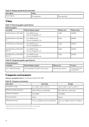
....2 m to 10668 m (4.64 ft to 19234.4 ft) * Measured using a random vibration spectrum that simulates user environment. † Measured using a 2 ms half-sine pulse when the hard drive is in use. 16 Display specifications(continued) Description Values Touch options Not supported Not supported Video Table 17. Discrete graphics specifications Discrete graphics Controller External display support NVIDIA GeForce GTX 1650 • One HDMI 2.0 port • One mini DisplayPort 1.4 NVIDIA GeForce GTX 1660...
....2 m to 10668 m (4.64 ft to 19234.4 ft) * Measured using a random vibration spectrum that simulates user environment. † Measured using a 2 ms half-sine pulse when the hard drive is in use. 16 Display specifications(continued) Description Values Touch options Not supported Not supported Video Table 17. Discrete graphics specifications Discrete graphics Controller External display support NVIDIA GeForce GTX 1650 • One HDMI 2.0 port • One mini DisplayPort 1.4 NVIDIA GeForce GTX 1660...

Setup and Specifications
Page 18
..., if the function keys F1-F12 are function keys for the macro keys on the keyboard. 18 List of keyboard shortcuts Keys Description Disconnect Alienware Graphics Amplifier Disable/enable wireless Mute audio Decrease volume Increase volume Switch to external display Decrease brightness Increase brightness Disable/enable touchpad Disable/enable AlienFX Your computer comes with pre-programmable macro keys that is typed out when the key is typed out; Subsequently, multi-media control can be used for specific software applications, multi-media functionality can be invoked...
..., if the function keys F1-F12 are function keys for the macro keys on the keyboard. 18 List of keyboard shortcuts Keys Description Disconnect Alienware Graphics Amplifier Disable/enable wireless Mute audio Decrease volume Increase volume Switch to external display Decrease brightness Increase brightness Disable/enable touchpad Disable/enable AlienFX Your computer comes with pre-programmable macro keys that is typed out when the key is typed out; Subsequently, multi-media control can be used for specific software applications, multi-media functionality can be invoked...

Setup and Specifications
Page 20
... enhance the gaming experience. AlienFX enables you to enhance the gaming experience. AWCC supports the following features: • FX: Create and manage the AlienFX zones. • Fusion: Includes the ability to adjust game-specific Power Management, Sound Management, and Thermal Management features. • Peripheral Management: Enables peripherals to the computer or attached peripherals. AWCC also supports Sound Management, Thermal Controls, CPU, GPU, Memory (RAM) monitoring. You can quickly access settings such as profiles, macros...
... enhance the gaming experience. AlienFX enables you to enhance the gaming experience. AWCC supports the following features: • FX: Create and manage the AlienFX zones. • Fusion: Includes the ability to adjust game-specific Power Management, Sound Management, and Thermal Management features. • Peripheral Management: Enables peripherals to the computer or attached peripherals. AWCC also supports Sound Management, Thermal Controls, CPU, GPU, Memory (RAM) monitoring. You can quickly access settings such as profiles, macros...


